P78 Series Controls for Dual Pressure and Hazardous Location Applications Installation Guide
5
Check the label inside the control cover for the model number, switch action, and electrical rating. Check the wiring
terminal designations on the control faceplate, and see the following wiring diagram when you wire the control. See
Figure 4 and Table 2. Also see Technical specifications
.
Use only cables and cable entries that are approved for R290 (propane) applications. Do not allow cables to come
into contact with sharp edges. Install cables with adequate stress relief to avoid pulling at the terminal.
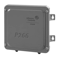
Table 2: P78 Switch wiring
LP/HP Description
LP A-C opens on pressure decrease.
A-B closes simultaneously.
HP A-C opens on pressure increase.
A-D closes simultaneously.
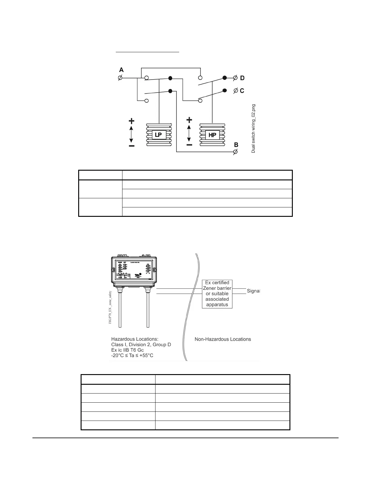
Table 3: Entity parameters (P78 Pressure Control parameters)
Parameter Maximum switch loads
Pi max (P max) 1 W
Ui Max (V max) 30 V
Ii Max (I max) 0.1 A
Ci max 0.5 nF
Li max 0.2 µH
Figure 4: P78 Switch wiring
Figure 5: Intrinsic safety protection method

 Loading...