Penn | TC3X21 | Installation Guide Rev. A | Part No. 24-7664-03833 | Page 1 of 14 | January 20, 2022
Small-Sized Basic Defrost Controller European Installation Guide
Basic controller for refrigerated cabinets, with energy-saving strategies
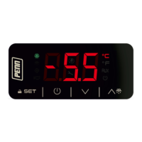
Figure 1: UI
Figure 2: Dimensions, mm (in.)
Figure 3: Drilling template, mm (in.)
Figure 4: Electrical connection
- Controller for normal temperature units
- Power supply for TC3X21N7x: 230 VAC
- Cabinet probe with a negative temperature coefficient (NTC)
- Door switch or multi-purpose input
- Cooling or heating operation
MEASUREMENTS AND INSTALLATION
For the dimensions and drilling template, see Figure 2 and Figure 3. Fit the controller to a panel
with the snap-in brackets supplied.
INSTALLATION PRECAUTIONS
- Ensure that the thickness of the panel is between 0.8 mm and 2.0 mm (1/32 and 1/16
in)
- Ensure that the working conditions are within the limits stated in the TECHNICAL
SPECIFICATIONS section.
- Do not install the device close to heat sources, equipment with a strong magnetic field,
in places subject to direct sunlight, rain, damp, excessive dust, mechanical vibrations or
shocks.
- In compliance with safety regulations, install the device correctly to ensure adequate
protection from contact with electrical parts. Fix all protective parts in such a way so as
to need the aid of a tool to remove them.
Important
- Use cables of an adequate wire gauge for the current running through them.
- To reduce any electromagnetic interference, connect the power cables as far away
as possible from the signal cables.
For the electrical connection diagram, see Figure 4.
Electrical connection diagram callouts
Door switch or multi-purpose
Power supply for TC3X21N7x: 230 VAC
PRECAUTIONS FOR ELECTRICAL CONNECTION
- If you use an electrical or pneumatic screwdriver, adjust the torque to a maximum of
0.5 N•m (4 in. lb).
- If you move the device from a cold to a warm place, the humidity may cause
condensation to form inside. Wait an hour before you switch on the power.
- Make sure that the supply voltage, electrical frequency, and power are within the set
limits. See TECHNICAL SPECIFICATIONS.
- Disconnect the power supply before you do any type of maintenance.
- Do not use the device as safety device.
- For repairs and further information, contact the Penn sales network.
1. Follow the instructions in MEASUREMENTS AND INSTALLATION to install the controller.
2. Power up the device as shown in ELECTRICAL CONNECTION and an internal test runs.
The test normally takes a few seconds. When it finishes the display switches off.
3. Configure the device as shown in Table 6.1 in SETTINGS.
For recommended configuration parameters for first-time use, see the following table.
Temperature unit of measurement
Check that the remaining settings are appropriate; see CONFIGURATION PARAMETERS.
4. Disconnect the device from the mains.
5. Make the electrical connection as shown in ELECTRICAL CONNECTION without powering
up the device.
6. Power up the device.
For a figure of the UI, see Figure 1.
UI callouts
Temperature unit of measurement
ON/STANDBY key and escape
DOWN key and additional functions menu
4.1 Switching the device on or off
If POF = 1, tap the ON/STAND-BY key for 4 s.
If the device is switched on, the display shows the P5 value, cabinet temperature by default. If
the display shows an alarm code, see ALARMS.
- Compressor protection active
- Setpoint setting active
- If device on, energy
saving active
- If device off, low
consumption active
If 30 s elapse and you do not press the keys, the display shows the “Loc” label and the keypad
locks automatically.
4.2 Unlocking the keypad
Tap any key for 1 s. The display shows the label “UnL”.
4.3 Setting the setpoint
Check that the keypad is not locked.
Tap the UP or DOWN key within 15 s to set the value within the
limits r1 and r2.
Tap the SET key or do not operate for 15 s.
4.4 Activating manual defrost (if r5 = 0, default)
Check that the keypad is not locked.
If P4 = 1, the defrost activates if the evaporator temperature is lower than the d2 threshold.
5.1 Navigating the additional functions menu
Before you begin, check that the keypad is not locked.
To access the additional functions menu, tap the DOWN key for
4 s.
To navigate to a label, tap the UP or DOWN key within 15 s.
To select a label, tap the SET key.
If you cannot edit the parameter, the value displays.
If you can edit the parameter, tap the UP or DOWN key to
navigate to the value that you want.
To set the parameter value, tap the SET key.
To exit the procedure, tap the ON/STAND-BY key, or do not
operate the controller for 60 s.
5.2 Additional functions menu
Use the additional functions menu to cycle through the labels in the following table.
6.1 Setting configuration parameters
Tap the SET key for 4 s. The display shows the label “PA”.
Tap the UP or DOWN key within 15 s to set the password. The
default password is "-19".
Tap the SET key or do not operate for 15 s. The display shows the
label “SP”.
Tap the UP or DOWN key to select a parameter.
Tap the UP or DOWN key within 15 s to set the value.
Tap the SET key or do not operate for 15 s.
Tap the SET key for 4 s, or do not operate for 60 s, to exit the
procedure.
6.2 Restoring the default factory settings and storing customized settings as
default
Important
- Check that the factory settings are appropriate; see CONFIGURATION PARAMETERS.
- When you store customized settings, you overwrite the default.
Tap the SET key for 4 s. The display shows the label “PA”.
Tap the UP or DOWN key within 15 s to set the value.
Restores the default factory settings
Stores customized settings as default
Tap the SET key or do not operate for 15 s. The display shows the
label “dEF” when you set the value “149” or the label “MAP”
when you set the value “161”.
Tap the UP or DOWN key within 15 s to set “4”.
Tap the SET key or do not operate for 15 s. The display shows "-
- -" flashing for 4 s, then the device exits the procedure.
Interrupt the power supply to the device.
Tap the SET key 2 s before step 6. to exit the procedure
beforehand.
- Check electrical connection
High condenser temperature
warning
High condenser temperature
alarm
- Switch the device off and on
- check C7
Multi-purpose input alarm
- Tap any key
- Check d2, d3, and d11
Purpose of the control device
Construction of the control device
Built-in electronic device
Black, self-extinguishing
Category of heat and fire resistance
75 mm x 33 mm x 39.5 mm (2 15/16 in. x 1
5/16 in. x 1 9/16 in.)
Mounting methods for the control device
Fit the controller to a panel with the snap-in
brackets supplied
Degree of protection provided by the covering
Fixed screw terminal blocks for wires up to
2.5 mm²
Maximum permitted length for connection cables
Power supply: 10 m (32.8 ft)
Analog inputs: 10 m (32.8 ft)
Digital inputs: 10 m (32.8 ft)
Digital outputs: 10 m (32.8 ft)
From 0°C to 55°C (from 32°F to 131°F)
From -25°C to 70°C (from -13°F to 158°F)
Relative humidity without condensate from
10% to 90%
Pollution status of the control device
Johnson Controls declares product compliance meets requirements of EMC,
LVD, and RoHS Directives.
UL Recognized Component, SDFY2.SA516; FCC Part 15 Subpart B Class A
UL Recognized Component, SDFY8.SA516; ICES-003 Class A
230 VAC (+10% -15%), 50/60 Hz (+/- 3Hz), max. 2 VA
Grounding methods for the control device
Rated impulse-withstand voltage
Software class and structure
1 for NTC probes (cabinet probe)
ß3435 (10 kohm at 25°C, 77°F)
-40°C to 105°C (-40°F to 221°F)
Input configurable for analog input (auxiliary probe) or digital
input (door switch or multi-purpose, dry contact)
1 electro-mechanical relay (compressor relay)
Additional features of Type 1 or Type 2 actions
3-digit custom display with function icons
This product is covered by a limited warranty, details of which can be found at
www.johnsoncontrols.com/buildingswarranty
Use of the software that is in (or constitutes) this product, or access to the cloud, or hosted
services applicable to this product, if any, is subject to applicable end-user license, open-
source software information, and other terms set forth at www.johnsoncontrols.com/techterms.
Your use of this product constitutes an agreement to such terms.
JOHNSON CONTROLS
C/O CONTROLS PRODUCT
MANAGEMENT
NO. 32 CHANGJIJANG RD NEW
DISTRICT
WUXI JIANGSU PROVINCE
214028
CHINA
JOHNSON CONTROLS
WESTENDHOF 3
45143 ESSEN
GERMANY
JOHNSON CONTROLS
507 E MICHIGAN ST
MILWAUKEE WI 53202
USA
Contact your local branch office:
www.johnsoncontrols.com/locations
Contact Johnson Controls:
www.johnsoncontrols.com/contact-us
Important
The device must be disposed of according to local regulations governing the collection
of electrical and electronic waste.
This document and the solutions contained therein are the intellectual property of Penn and thus
protected by the Italian Intellectual Property Rights Code (CPI). Penn imposes an absolute ban on the
full or partial reproduction and disclosure of the content other than with the express approval of Penn.
The customer (manufacturer, installer or end-user) assumes all responsibility for the configuration of the
device. Penn accepts no liability for any possible errors in this document and reserves the right to make
any changes, at any time without prejudice to the essential functional and safety features of the
equipment.