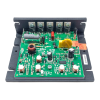
FIG. 1 – BASIC KBIC
®
TABLE 4. FUSE SELECTION CHART*
90 VDC Motor 180 VDC Motor Approx.
Motor Current
(DC Amps)
Fuse Rating
(AC Amps)
HORSEPOWER
1/100 1/50 0.1 2/10
1/50 1/25 0.2 3/10
1/30 1/15 0.3 1/2
1/20 1/10 0.5 3/4
1/15 1/8 0.7 1
1/10 1/5 1.0 1
1/8 1/4 1.3 2
1/6 1/3 1.7 3
1/4 1/2 2.5 4
1/3 3/4 3.3 5
1/2 1 5.0 8
3/4 1 7.5 12
1 2 10.0 15
1 3 15.0 25
*Note: Specific applications may require a different fuse value than
indicated. This is based on several factors such as ambient temperatures,
duty cycle, motor form factor and CL setpoint.
FIG. 1 – FEATURES AND FUNCTIONS
(1) Plug-in Horsepower Resistor
®
(2) Mounting Holes for Armature and AC Line Fuses
(3) Trimpots: MIN, MAX, ACCEL, IR & CL
(4) Auxiliary Heatsink (optional) (see fig. 2, p. 7)
TABLE 5 – PLUG-IN HORSEPOWER RESISTOR® CHART
(1)
Motor Horsepower
(2)
Approx.
Motor
Current
(DC Amps)
Plug-in
Horsepower
Resistor
Value (Ohm)
Individual
Plug-in
Horsepower
Resistor® P/N
Armature Voltage
90VDC
Armature Voltage
180VDC
1/100 1/50 0.1 1.0 9833
1/50 1/25 0.2 0.51 9834
1/30, 1/25 1/15 0.35 0.35 9835
1/20 1/10 0.5 0.25 9836
1/15, 1/12 1/6 0.8 0.18 9837
1/10, 1/8, 1/6 1/4 1.3 0.1 9838
1/4 1/2 2.5 0.05 9839
1/3 3/4 3.3 0.035 9840
1/2 1 5.0 0.025 9841
3/4 1 7.5 0.015 9842
1 2 10.0 0.01 9843
1 3 15.0 0.006 9850
Notes:
(1) Motor horsepower and armature voltage must be specified in order
to select correct Plug-in Horsepower Resistor
®
.
(2) For motor horsepower not indicated use lower value Plug-in
Horsepower Resistor
®
.
5
iii. INTRODUCTION
Thank you for purchasing the KBIC
®
"Standard of the Industry" DC motor speed control. They are designed for applications
demanding good performance, high reliability and low cost. The controls are fabricated with components that have proven reliability,
including MOV transient protection, which is used to protect the power bridge. Integrated circuitry is used to provide an uncomplicated
design with superior load and line voltage regulation. The patented Direct-Fed™ current limit circuit protects the motor and control
against overloads by limiting the maximum level of output current. It also prevents motor failure due to demagnetization of the magnets
of PM motors. Acceleration start (adjustable from 0.5 to 4 seconds) provides a smooth start each time the AC power is applied.
A unique feature of the KBIC
®
control is the Plug-in Horsepower Resistor
®
. It eliminates the need to recalibrate IR Comp. and CL
when the control is used over a wide range of motor horsepower. Additional versatility is achieved by using the Auxiliary Heatsink
(optional) which is used to double the horsepower rating of each model. The output of the control is a linear function of potentiometer
rotation. The KBIC
®
can also be operated in a voltage following mode by supplying an isolated analog signal (0-7 VDC) to the input
terminals P2(+) and F-. If an isolated input signal is not available, the optional Barrier Terminal Board Signal Isolator (SI-5) can be used.
The controls are terminated as standard with Q-D terminals. A Barrier Terminal Board is available which incorporates both line and
armature fuses.
The Inhibit™ circuit (Terminals I1 and I2) is provided to electronically disconnect the armature output voltage. Another standard
feature is Auto Inhibit. This circuit prevents false starts and high surge currents when cycling the KBIC
®
control with the AC line.
All models are UL Recognized for the USA and Canada and CE approved.
I. APPLICATION INFORMATION
A. Motor Type – The KBIC
®
is designed for Permanent Magnet (PM), Shunt Wound and Universal (AC/DC) motors. Controls
operated on 115 volt AC inputs are designed for 90 volt SCR rated motors. Controls operated on 230 volt AC inputs are
designed for 180 volt SCR rated motors. Use of higher voltage motors will result in reduction of available MAX speed. Also,
if motor is not an SCR rated type, the actual AC line amperage at full load should not exceed the motor's DC nameplate
rating.
B. Torque Requirements – When replacing an AC induction motor with a DC motor and speed control, consideration must
be given to the maximum torque requirements. The full load torque rating of the DC motor must be equal to, or greater than,
that of the AC motor.
C. Acceleration Start – The KBIC
®
contains an adjustable acceleration start feature which allows the motor to smoothly
accelerate from 0-full speed over a time period of 0.5-4 seconds. The "ACCEL" is factory set at 2 seconds.
D. Limitation in Use – The KBIC
®
controls are designed for use on machine applications.
E. Armature Switching – Do not switch the armature without taking proper precautions. (See sec. IV, p. 11)
CAUTION
Consult factory before using on constant horsepower applications such as saws or drill presses. Do not use in
explosive atmosphere.
Be sure the KBIC
®
is used within its maximum ratings. Follow all installation instructions carefully. (Refer to section II.)
6
 Loading...