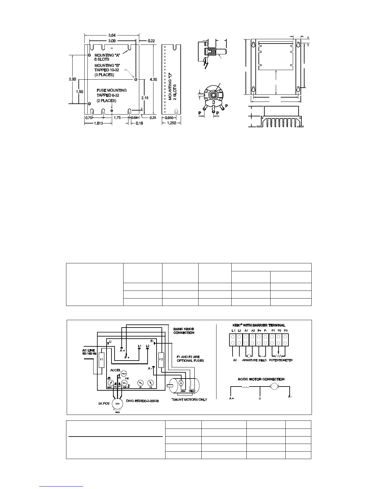
FIG. 2 – MECHANICAL SPECIFICATIONS
3
2
1
CONTROL
DWG #:D2600-1-00281
1.375
1.250
7.000
3.110
6.250
5.625
5.625
0.500
0.982
.438
0.125
PIN
ROTATION
ANTI-
BUSHING
3/8-32
1/4" ROUND
ALUM. SHAFT
3/8 1/2
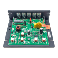
POTENTIOMETER OPTIONAL AUXILIARY HEATSINK
II. INSTALLATION INSTRUCTIONS
A. Location and Mounting – The KBIC
®
controls should be mounted on a flat surface and located in an area where it will
not be exposed to contaminants such as water, metal chips, solvents or excessive vibration. When mounting in an
enclosure, the air space should be large enough to provide adequate heat dissipation. The maximum allowable ambient
temperature at full rating is 45 ºC/113 ºF. Consult factory if more information is required.
B. Initial Setup and Wiring.
1. Install proper size Plug-in Horsepower Resistor
®
(See chart).
2. The KBIC can be connected to a standard 115V or 230V (±15%) 50/60 Hz AC line based on model selected [Be sure
the AC input voltage corresponds to the control voltage rating and the motor rating (e.g. 90-130VDC motor on 115VAC
and 180VDC motor on 230VAC)].
3. Follow the recommended supply wire sizes as per table 6, p. 8.
4. Follow the NEC and other electrical codes that apply.
CAUTION: Separate branch protection must be provided on 240V circuits. Do not fuse neutral or grounded
conductors.
5. Connect control in accordance to connection diagram - See fig. 3, p. 8.
6. When using a step-down transformer (440 VAC to 220 VAC) be sure the VA rating of the transformer is at least 3 times
the VA rating of the motor.
7
TABLE 6
Minimum Supply Wire
Size Requirements
*Minimum Recommended
Wire Size
MAX. MOTOR
CURRENT
(DC AMPS)
MAX. MOTOR
HP 90V
MAX. MOTOR
HP 180V
MINIMUM WIRE SIZE (AWG) Cu only
MAX. 50 FOOT
RUN
MAX. 100 FOOT
RUN
6 0.5 1 16 14
12 1 2 14 12*
16 1.5 3 12 12
FIG. 3 – CONNECTION DIAGRAM
TABLE 7
Field Connections (Shunt-wound Motors Only)
Caution: Shunt-wound motors may be
damaged if field remains energized without
motor rotating for an extended period of time.
AC LINE VOLTAGE FIELD VOLTAGE (VDC) FIELD CONNECTION FIELD TYPE
115 100 F+, F- Full Voltage
115 50 F+, L1 Half Voltage
230 200 F+, F- Full Voltage
230 100 F+, L1 Half Voltage
8
 Loading...