Note: The MIN speed adjustment will affect the MAX speed setting. Therefore, it is necessary to readjust the MAX speed after
the MIN speed, and it may be necessary to repeat the sequence until both the MIN and the MAX speeds are set to the
desired levels.
D. Current Limit (CL/Torque Adjustment) – CL circuitry is provided to protect the motor and control against overloads. The
CL also limits the inrush current to a safe level during startup. The CL is factory set to approximately 1.5 times the full load
rating of the motor. (CL trimpot is nominally set to approx. 50% of full CW rotation.)
Note: The correct value Plug-in Horsepower Resistor
®
must be installed in order for the CL and IR comp. to operate properly.
Calibration of the CL & IR comp. is normally not required when the proper Plug-in Horsepower Resistor
®
is
installed.
To set the CL to factory specifications adjust as follows:
1. Set main speed potentiometer at approximately 30 - 50% CW rotation. Set CL trimpot to full CCW position.
2. Connect a DC ammeter in series with the armature lead.
3. Lock shaft of motor (be sure CL pot is in full CCW position). Apply power and rotate CL pot CW slowly until DC ammeter
reads 1.5 times motor rating (do not exceed 2 times motor rating). Note: Complete this step within 5 seconds to avoid
damaging motor.
Note: If only an AC ammeter is available, it can be installed in series with AC input line. Follow above instructions; however,
set AC amperage at 0.75 times motor rating.
E. IR Compensation Adjustment – IR compensation is provided to substantially improve load regulation. If the load presented
to the motor does not vary substantially, the IR adjustment may be set at a minimum level (approximately 1/4 of full setting).
The control is factory adjusted to approximately 3% regulation. If superior performance is desired (less than 1% speed
change of base speed from 0 to full load), then the IR comp. should be adjusted as follows:
Note: Excessive IR comp. will cause control to become unstable, which causes motor cogging.
1. Set IR comp. trimpot at approximately 25% of CW rotation. Run motor unloaded at approximately 1/3 speed and record
RPM.
2. Run motor with maximum load and adjust IR comp. trimpot so that the motor speed under load equals the unloaded speed
per step 1.
3. Remove load and recheck unloaded RPM. If unload RPM has shifted, repeat procedure for more exact regulation. The
control is now compensated to provide minimal speed change under large variations of applied load.
IV. SWITCHING CIRCUITS
A. AC Line Switching – The KBIC
®
can be safely turned "on" and "off" rapidly using the AC Line (no waiting time is required).
Auto Inhibit
®
circuitry contained in the KBIC
®
automatically resets critical components each time the AC line is interrupted.
This, along with Acceleration Start and CL, will provide a smooth start each time the AC line is connected.
11
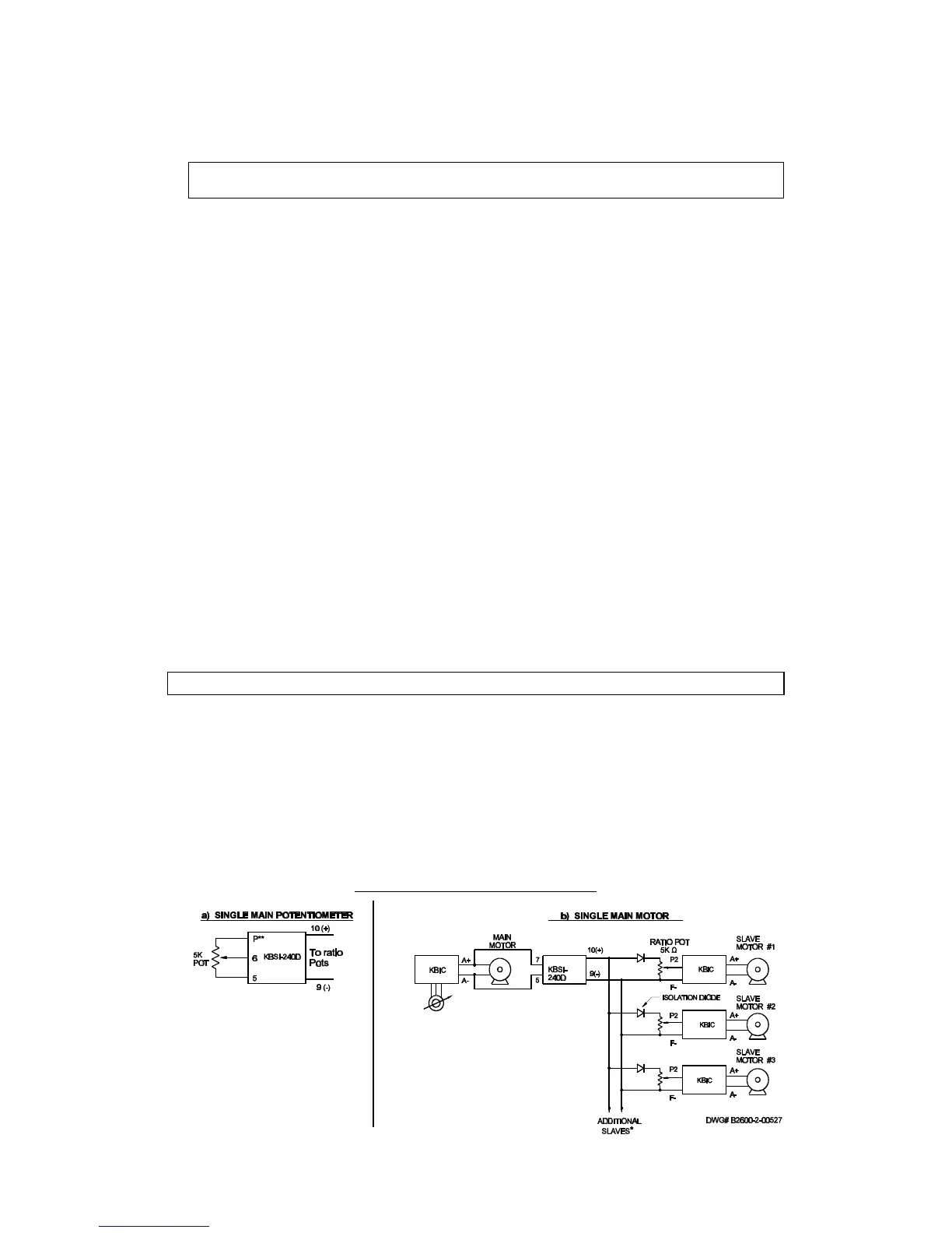
* A 10K ratio potentiometer is used to control up
to (10) "slave" motors. If a 5K ratio
potentiometer is used, up to (5) "slave" motors
can be controlled.
1) Multiple KBIC
®
controls should be powered
from the same phase AC line.
2) The positive output terminal to each speed
control must be installed with a 1A-600PIV
isolation diode.
Warning: Do not disconnect and reconnect the Armature with the AC line applied or catastrophic failure will result.
B. Armature Switching – If the armature is to be disconnected and reconnected with AC power applied, the Inhibit Circuit™ must
be simultaneously activated and deactivated. Connect I1 and I2 together to activate the Inhibit Circuit™. See fig. 5B for
dynamic brake circuit.
C. Reversing and Dynamic Braking – KB has developed the APRM
®
* which provides anti-plug "instant" reversing and solid state
dynamic braking. The APRM
®
is built in as standard in all KBCC-R suffix models and in all KBPB™ models. *Patented.
FIG. 5 APPLICATIONS
A. Master/Slave Connections. The KBIC can be used with the KBSI to drive multiple motors:
(a) From a single main potentiometer
(b) From a single main motor.
FIG. 5A – MASTER SLAVE CIRCUIT
** connect high side of potentiometer
to terminal “P” (” QD)
12
 Loading...