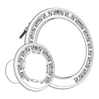
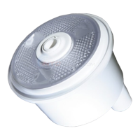
The Pentair IntelliBrite Architectural Series Pool/Spa Light is a sophisticated lighting solution designed for both aesthetic enhancement and practical illumination of pools and spas. This device offers a range of features for both white and color lighting, along with detailed installation, operation, and maintenance instructions.
Function Description:
The IntelliBrite Architectural Series Pool/Spa Light provides versatile lighting options for aquatic environments. It can function as a white light, offering standard illumination for your pool or spa. Alternatively, it can operate as a color light, providing multiple colors and effects. Users can choose from seven pre-programmed color light shows or five fixed colors to create dramatic and customized lighting effects. The lights can be manually controlled using a standard wall-mount light switch, allowing for synchronized operation of multiple lights connected through a junction box. For advanced control, IntelliBrite lights are compatible with Pentair automation systems and light controllers, offering automated management of lighting displays.
Important Technical Specifications:
The manual outlines specific electrical installation requirements for both USA and Canada, emphasizing safety and compliance with national electrical codes.
- Voltage Options: The lights are available in 12V and 120V configurations.
- Transformer Usage (12V Lights Only):
- When using multiple 12 VAC lights with a 300 Watt transformer, a maximum of three lights should be used.
- For multiple lights, the distance between the transformer and the lights should not exceed 100 feet (30.5 m).
- For a single light, the distance between the transformer and the light should not exceed 200 feet (61 m).
- For longer cable lengths, the transformer should be set to 14 VAC.
- Junction Box Placement (USA):
- The low-voltage transformer and/or junction box must be at least 8 inches (20.3 cm) above the maximum water level and at least 4 inches (10.2 cm) above ground level or pool/spa deck, whichever is higher.
- The junction box must be no less than 4 feet (1.2 m) from the inside wall of the pool/spa, unless a solid fence, wall, or permanent barrier separates them.
- Junction Box Placement (Canada):
- The GFCI breaker or transformer must be at least 3 meters (10 feet) from the edge of the pool/spa.
- The junction box must be installed above the maximum water level of the pool/spa, with its top at or above the pool/spa deck level, in a location that does not obstruct, and where deck water drains away from it. It must also be sealed to the conduit to prevent water entry.
- Bonding and Grounding:
- For 120V lights in the USA, they MUST be connected to a Ground Fault Circuit Interrupter (GFCI) with an appropriately rated circuit breaker.
- The light fixture must be bonded to all other metallic items within 5 feet (1.5 m) of the pool/spa using an #8 AWG bond wire (USA) or #6 AWG bond wire (Canada). The bonding lug is at the rear of the niche.
- If non-metallic conduit is used, an #8 AWG (USA) or #6 AWG (Canada) bonding/grounding wire must be installed through the conduit from the Junction Box to the bonding/grounding lug inside the niche. The connection must be sealed to prevent corrosion.
- Niche Installation: The top edge of the light lens, when installed, must be at least 18 inches (45.7 cm) below the maximum water level (USA) or 60 centimeters (23.6 inches) below the maximum water level (Canada).
- Safety Isolation Transformer: For light operation, only a safety isolation transformer should be used.
- Pentair Niches: Only Pentair niches should be used to ensure proper bonding and grounding connections.
- Dimmer Circuits: The light cannot be used on a dimmer circuit, as this will cause permanent damage.
- Mounting Surfaces: Luminaires are not suitable for direct mounting on normally flammable surfaces; they are ONLY suitable for mounting on non-combustible surfaces.
- Cord Length: The manual provides replacement parts with various cord lengths, including 30 ft (9.2 m), 50 ft (15.2 m), 100 ft (30.5 m), 150 ft (45.7 m), and 250 ft (76.2 m) for different wattages and light types (white, warm white/turtle, color).
Usage Features:
- Manual Control: Lights can be controlled via a standard wall switch. Turning the switch off and on a specific number of times (1-12) selects one of seven pre-programmed color light shows or five fixed colors.
- Light Shows: SAM Mode (white, magenta, blue, green), Party Mode (rapid color changes), Romance Mode (slow color transitions), Caribbean Mode (blues and greens), American Mode (red, white, blue), California Sunset Mode (orange, red, magenta), Royal Mode (richer, deeper tones).
- Fixed Colors: Blue, Green, Red, White, Magenta.
- Hold Feature: Users can save the current light show or fixed color by cycling the power 13 times.
- Recall Feature: The last saved light show or fixed color can be activated by cycling the power 14 times.
- Automatic Control: IntelliBrite lights can be integrated with Pentair automation systems and light controllers for automated operation.
- Safety During Operation: The light must be completely submerged in water before operation. During manual color selection, there will be a brief period of no illumination, requiring precautions to avoid accidents.
Maintenance Features:
The manual provides detailed instructions for replacing the light assembly and its internal components, emphasizing safety and the use of new parts for reassembly.
- Replacing the Light Assembly:
- Always disconnect power at the circuit breaker before servicing.
- Remove the pilot screw from the face ring.
- Remove the light assembly from the niche, placing it on the deck.
- Cut the cord about 12 inches (30.5 cm) from the back of the light assembly.
- Remove the junction box cover, disconnect wires, and pull the cord through the conduit. Taping the new cord to the old one can facilitate feeding.
- Feed the new cord through the conduit, leaving at least 4 feet (1.2 m) coiled in the niche for future servicing while the pool/spa is filled.
- Cut the cord at the junction box, leaving 6 inches (15.3 cm) for connections.
- Strip insulation and connect the three light wires (Black to Power, White to Common, Green to Ground) to the corresponding circuit wires in the junction box.
- Secure the junction box cover and tighten the pilot screw (using only the provided screw for electrical grounding).
- Removing and Disassembling the Pool Light:
- Disconnect all power to the light. DO NOT service while in the pool.
- Loosen the pilot screw (do not remove it) from the face ring.
- Remove the light assembly from the niche and place it on the pool deck.
- Place a clean cloth and turn the light over, resting the lens on the cloth.
- Loosen the bolt tensioning the wire clamp and carefully remove the clamp hardware. Discard the old wire clamp and hardware.
- Lift the light housing away from the lens and face ring.
- Lift the lens away from the face ring.
- Remove and discard the orange gasket from the lens.
- Crucially, a NEW lens gasket and wire clamp MUST be used each time the light is reassembled.
- Replacing the Fuse Assembly (12V Pool Lights Only):
- Only 12V pool lights have a replaceable fuse assembly; 120V pool lights and all spa lights do not.
- Disconnect both fuse-board flag connectors from the LED board.
- Press the release lever on the fuse-harness connector and separate the fuse assembly.
- Plug the new fuse-harness connector into the light's fuse harness until it locks.
- Connect the new fuse-board flag connectors to the LED board terminals (do not press too hard).
- Reassemble the light.
- Replacing the Pool Light LED Boards (Pool Lights Only):
- Only pool lights have replaceable LED boards; spa light LED boards are NOT replaceable.
- Always use the same type and wattage LED boards.
- Disconnect the two wires from the light housing to the middle LED board.
- Remove the eight retaining nuts securing the LED boards to the light housing.
- Remove the plastic LED refractor from the middle LED board.
- Remove all three LED boards and the thermal pad from the light housing.
- Install the new thermal pad over the board mounts.
- Ensure LED refractors are installed on both new right and left LED boards.
- Place the larger middle LED board over the five central board mounts, ensuring wires are not pinched.
- Place the middle LED refractor onto the new middle LED board.
- Place the right and left LED boards over their respective board mounts.
- Reinstall the eight retaining nuts with a 5/16-inch nut driver (do not overtighten).
- Reconnect fuse assembly wires to the middle LED board if necessary.
- Reassemble the light.
- Reassembling the Pool Light:
- Ensure the black lens O-ring is seated inside the orange lens gasket.
- Stretch the gasket around the outer edge of the lens, with "TOP" positioned correctly. Ensure even installation.
- Place the light housing on its base, then the lens/gasket, and finally the face ring.
- Rotate the face ring until the pilot screw aligns with the notch in the inner edge of the light housing.
- Place the new wire clamp into the six face ring hooks, with hooked ends facing away from the lens/housing. Ensure the clamp is held by all six hooks for a proper seal.
- Ensure both ends of the wire clamp are at a 45-degree angle to the pilot screw.
- Pass the clamp bolt through both ends of the wire clamp, thread the washer and nut, and tighten until the ends are within 3/16 inch (5 mm) of each other.
- Reinstall the light assembly into the niche.
- Spa Light Maintenance: Similar removal, disassembly, and reassembly procedures are provided for spa lights, with specific part numbers for 12V and 120V spa light replacement parts. The key difference is that spa lights do not have replaceable fuse assemblies or LED boards.