3
MODELS 411 & 481, 412, 413 & 483
However, when the pump is exposed to dirt contamination, high
temperatures (200F. or above) or a wet location, the oil may
have to be changed every 2 or 3 months.
The motor that drives your Aurora pump may or may not
require lubrication. Consult the manufacturer’s recommenda-
tions for proper maintenance instructions.
REPAIRS
The pump may be disassembled using the illustrations and text
provided. Although complete disassembly is covered, it will
seldom be necessary to completely disassemble your Aurora
Pump.
The illustrations accompanying the disassembly instructions
show the pump at various stages of disassembly. The illustra-
tions are intended to aid in the correct identification of the parts
mentioned in the text.
Inspect removed parts at disassembly to determine their
reusability
. Cracked castings should never be reused. All pack-
ing and gaskets should be replaced with new ones at reassembly
simply as a matter of economy; they are much less expensive to
replace routinely than to replace as the need accrues. In general
it is economical to return to the manufacturer for repair only the
motor and motor controller.
DISSASSEMBLY OF THE PUMP
- Disassemble only what is
needed to make repairs or accomplish inspection. Proceed to
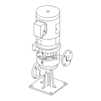
disassemble the pump as follows: (see figure 4 for Model 411
& 481, Figure 5 for Model 412 and Figure 6 for Model 413 &
483.
1. Break the electrical connections to motor or take other
steps needed to prevent drive unit from being unintentionally
energized during disassembly.
2. Close such valves or flow-control devices necessary to
make certain flow of liquid will no take place during disas
s
embly.
NOTE
Discharge and suction piping need not be disturbed unless
complete pump assembly is to be removed.
3. Drain liquid from pump by removing plugs (1 and 2).
Disconnect any flushing, cooling, by-pass lines that are con
nected to parts that will be removed.
4. Loosen and remove capscrews (6) securing casing half (8)
to remainder of pump assembly.
NOTE
If pump being disassembled is size 4x5x11 or larger, remove
capscrews (7) also before attempting to separate casing ha
lves
If possible drain and/or flush pump to remove any corrosive
or toxic liquid before attempting further disassembly. Many
units will not have drain taps.
5. Make certain all securing capscrews are removed, then
carefully remove casing half (8) using hoist or crane with a
sling attached around cast hooks on the casing and under the
casing.
Use extreme care when casing comes loose that it does not
drop out of sling, as this would cause extensive damage to
other components of p
ump.
6. Remove gasket (9) and scrape mating surface of casing
halves to remove pieces of gasket which have adhered in sep-
aration. Take care not to scratch or mar mating surface.
7. On Model 411, 481 and 413, 483 loosen flexible coupling
and slide the halves apart. On Model 412 pumps remove
flexible shafting.
B. Casing half removed.
C. Rotating element removed from casing half.
CAUTION
D. Outboard rotating element components removed
illustrating disassembly order.
E. Sleeve and thrust washer removed.
 Loading...