8
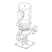
20. On model 413 & 483 pumps, set the motor on motor bracket (74) and fasten them together with capscrews (73). Slide the flexible
coupling halves onto the pump and motor shafts. Attach motor bracket to casing half (69) with capscrews (75). Connect flexible
coupling halves. On model 412 pumps, attach flexible shafting. Ideal joint operating angle is 1” to 5”. On Model 411 pumps, if lower
casing was removed from the base, see section on installation for proper methods of realig
ning pump to motor and piping.
21. Replace any flushing, cooling, by-pass or drain lines that were removed from the pump. Connect electricity back to the motor.
STARTING PUMP AFTER REASSEMBLY
– Do not start pump until all air and vapor have been bled and making sure that there
is liquid in pump to provide necessary lubrication.
NOTE
Do not over tighten standard packing assembly before returning unit to operation. Jog the pump to check for proper rotation. Then
allow pump to run for a short time, gradually tighten nuts (18) until dripping has been reduced to its normal level.
1. Plug
2. Plug
6. Capscrew
7. Capscrew
8. Casing
9. Gasket
10. Grease Fitting
12 Plug
18. Nut
19. Washer
20. Clamp
21. Gland Half
22. Swing Bolt
23. Packing
24. Key
25. Capscrew
26. Bearing Cap
27. Pin
28. Wearing Ring
29. Protector
31. Capscrew
32. Cartridge Cap
34. Gasket
35. Retaining Ring
35A. Retaining Ring
36. Cartridge
37. Grease Seal
38. Bearing
39. Slinger
40. Slinger
41. Capscrew
42. Cartridge Cap
43. Grease Seal
44. Gasket
45. Cartridge
46. Grease Seal
47. Bearing
48. Sl
inger
49. Gland
50. O-Ring
51. O-Ring
52. Lantern Ring
53. Seal
54. Collar
55. Setscrew
56. Bushing
57. Sleeve
58. O-Ring
59. Impeller
60. Sleeve Pin
61. Wearing Ring
62. O-Ring
63. Key
64. Sleeve
65. Shaft
66. Pin
67. Pin
68. Pin
69. Casing
70. Drivescrew
71. Nameplate
72. Setscrew
78. Setscrew
79. Sleeve Collar
MODELS 411 & 481, 412, 413 & 483
MODEL 412 LIST OF PARTS (See Figure 5)
1. Plug
2. Plug
6. Capscrew
7. Capscrew
8. Casing
9. Gasket
10. Grease Fitting
12 Plug
18. Nut
19. Washer
20. Clamp
21. Gland Half
22. Swing Bolt
23. Packing
24. Key
25. Capscrew
26. Bearing Cap
27. Pin
28. Wearing Ring
29. Protector
31. Capscrew
32. Cartridge Cap
34. Gasket
35. Retaining Ring
35A. Retaining Ring
36. Cartridge
37. Grease Seal
38. Bearing
39. Slinger
40. Slinger
41. Capscrew
42. Cartridge Cap
43. Grease Seal
44. Gasket
45. Cartridge
46. Grease Seal
47. Bearing
48. Sl
inger
49. Gland
50. O-Ring
51. O-Ring
52. Lantern Ring
53. Seal
54. Collar
55. Setscrew
56. Bushing
57. Sleeve
58. O-Ring
59. Impeller
60. Sleeve Pin
61. Wearing Ring
62. O-Ring
63. Key
64. Sleeve
65. Shaft
66. Pin
67. Pin
68. Pin
69. Casing
70. Drivescrew
71. Nameplate
72. Setscrew
78. Setscrew
79. Sleeve Collar
MODEL 413 & 483 LIST OF PARTS (See Figure 6)
MODEL 411 & 481 LIST OF PARTS (See Figure 4)
 Loading...