P/N • Núm/Pte. • Réf. 991020 00 2 Rev. C 5-11-01
SECTION I. FILTER INSTALLATION.
1. The filter should be mounted on a level concrete slab. Position the filter
so that the instructions, warnings and pressure gauge are visible to the
operator. Also, position the filter so that the piping connections, control
valve and drain port are convenient and accessible for servicing and
winterizing.
2. Install electrical controls (e.g., on/off switches, timers, control systems,
etc.) at least five (5) feet from the filter. This will allow you enough
room to stand clear of the filter during system start up.
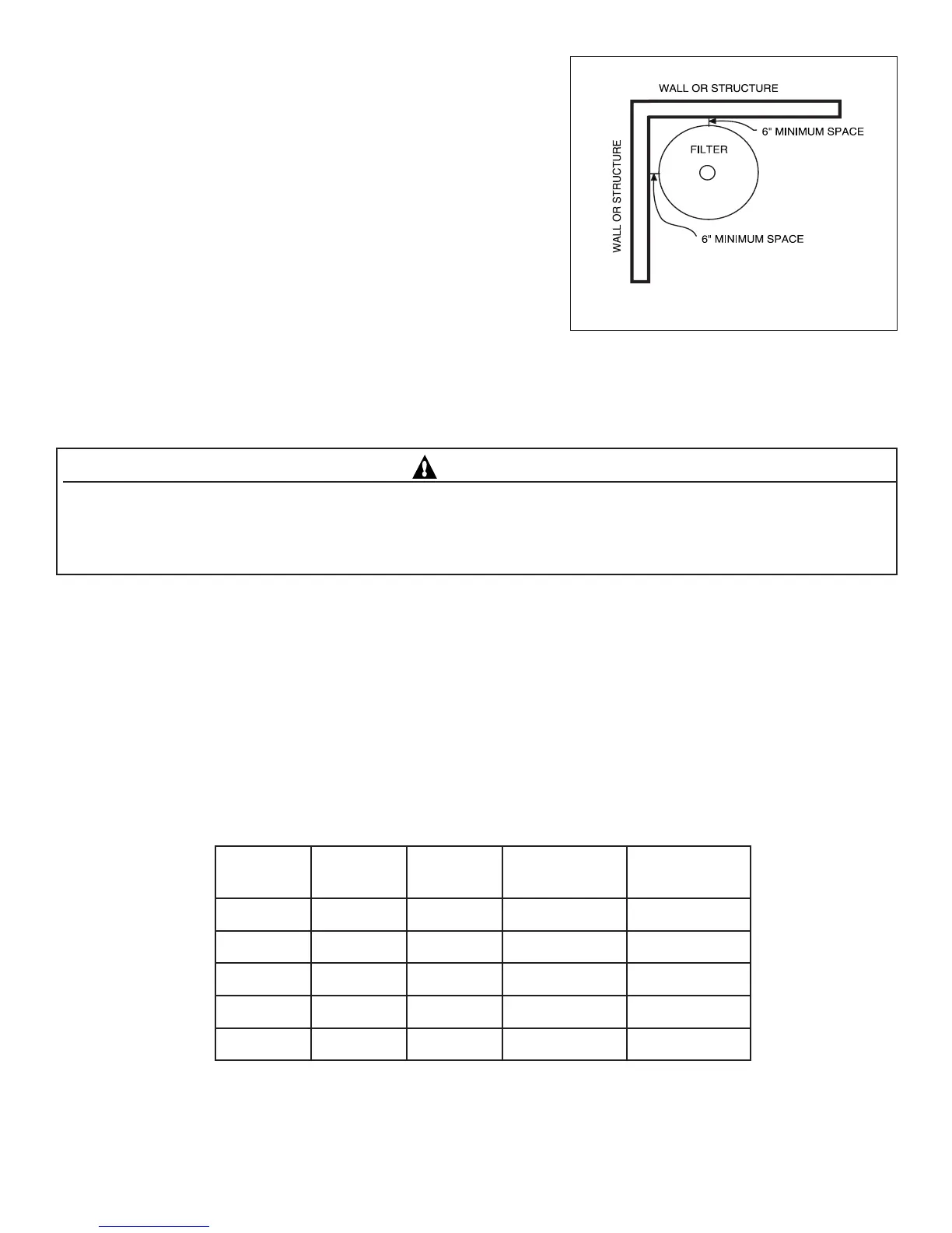
3. Provide sufficient clearance around the filter to permit visual
verification that the clamp is properly installed, see Figure 1.
4. Provide sufficient space above the filter to remove the control valve for
cleaning and servicing. This distance will vary with the model of filter you are using. See Table 1 for the required verticl
clearance.
5. Make all plumbing connections in accordance with local plumbing and building codes. Filter plumbing connections are
provided with an O-ring seal. Use only a silicone based lubricant on the O-rings. Do not use pipe joint compound, glue or
solvent on the bulkhead connections to avoid damage to the O-rings.
C AUTION
For Multiport cont r ol valves with threaded ports use only Teflon ta pe, 100% pure Teflon paste
(
non-pet roleu
m
base
)
,
Per
m
atex #2 sealant on all threaded pipe connections, excep t fittings with
O
-rings.
U
se of other pipe jo int co
m
pounds can
da
m
age co
m
ponents of this syste
m
and cause leaks. For control valves w ith slip ports, use only AB
S
to PVC solven t welding
adhesive.
6. For the maximum working pressure of this filter see Table 1. Never subject this filter to pressure in excess of this amount -
even when conducting hydrostatic pressure tests. Pressures above maximum working pressure can cause the valve or other
plumbing to be blown off, which can result in severe injury, death or property damage.
When performing hydrostatic pressure tests or when testing for external leaks of the completed filtration and plumbing
system, insure that the Maximum Pressure that the filtration system will be subjected to DOES NOT EXCEED THE
MAXIMUM WORKING PRESSURE OF ANY OF THE COMPONENTS CONTAINED WITHIN THE SYSTEM. In
most cases, the maximum pressure will be stated on each component of the system.
If doubt exists as to the pressure to which the system will be subjected, install an ASME approved automatic Pressure Relief
or Pressure Regulator in the circulation system for the lowest working pressure of any of the components in the system.
ledoM
aerAretliF
.tf.qs
dnaSfo.sbL
.qer
gnikrowxaM
erusserp
ecnaraelClacitreV
deriuqeR
8136.108isp53.ni54
020.2031isp53.ni54
225.2051isp05.ni54
625.3522isp05.ni94
036.4053isp05.ni15
Table 1.
Figure 1.
 Loading...