P/N • Núm/Pte. • Réf. 991020 00 4 Rev. C 5-11-01
C AUTION
The following infor
m
ation should be read carefu lly since it outlines the proper
m
anner of care and operation for your filter syste
m
.
As a resu lt of foll owing these instructions and taking the necessary preventat ive care , you can expect
m
axi
m
u
m
effici ency and life
fro
m
your filtration syste
m
.
B. FILTER MEDIA.
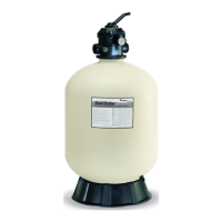
1. Media - Your sand filter uses a #20 grade silica filter sand for its media (.45 - .55 mm). It should be free of all limestone or
clay. Most pool supply and building material stores carry silica sand. See Table 1 for the appropriate amounts of silica sand.
2. Remove the valve from your filter and install the sand funnel on the top of the filter tank. Fill the tank about half full of water.
Pour the silica sand into the top of the filter tank slowly, so that the weight does not damage the lateral assembly in the bottom
of the tank or the overdrain plumbing near the top of the tank.
3. After filling the filter tank with the appropriate amount of silica sand, remove the sand funnel and wash away any loose sand
from the opening of the filter tank.
4. To complete the top mounted control valve installation, follow instructions in Section C, Valve and Clamp Installation
Instructions.
C AUTION
For Multiport c ontrol valves with threaded ports use only Teflon tape, 100% pure Teflon paste
(
non-pet roleu
m
base
)
, or Per
m
atex
#2 sealant on all threaded pipe connections, except fittings with
O
-rings.
U
se of other pipe join t co
m
pounds can da
m
age
co
m
ponents of this syste
m
and cause leaks. For control valves w ith slip ports, use only AB
S
to PVC solven t welding adhesive.
5. For the maximum working pressure of this filter see Table 1. Never subject this filter to pressure in excess of this amount -
even when conducting hydrostatic pressure tests. Pressures above the maximum working pressure can cause the lid to be
blown off, which can result in severe injury, death or property damage.
When performing hydrostatic pressure tests or when testing for external leaks of the completed filtration and plumbing
system, insure that the Maximum Pressure that the filtration system will be subjected to DOES NOT EXCEED THE
MAXIMUM WORKING PRESSURE OF ANY OF THE COMPONENTS CONTAINED WITHIN THE SYSTEM. In most
cases, the maximum pressure will be stated on each component of the system.
If doubt exists as to the pressure to which the system will be subjected, install an ASME approved automatic Pressure Relief
or Pressure Regulator in the circulation system for the lowest working pressure of any of the components in the system.
C. VALVE AND CLAMP INSTALLATION INSTRUCTIONS.
These instructions MUST BE FOLLOWED EXACTLY to prevent the valve from blowing off during system restart or
later operation:
1. Before working on any part of the circulating system, (e.g. clamp, pump, filter, valves, etc.) perform the following steps:
a. Turn the pump off and shut off any automatic controls to ensure that the system is not inadvertently started during
servicing.
b. Wait until all pressure is relieved. Never attempt to assemble, disassemble or adjust the filter valve clamp while
there is any pressure in the filter.
2. Be sure that the chamfered sealing surface inside of the brass, or plastic flange at the top of the tank is clean and free of any
sand or debris. Apply a light coating of SILICONE BASE LUBRICANT to the O-ring/gasket for the top mounted control
valve, and install into the opening in the top of the filter tank.
a. For the top mount control valve: ensure the center pipe slips into the bore of the control valve.
3. Install valve in the following manner:
a. Position the top mounted control valve so that the port locations are in the desired position. Control valve port locations
are labeled with the location to which they should be connected.
4. Open the filter valve clamp and install both halves over the flanges of the filter tank and the control valve. Check to ensure
that the valve clamp is securely installed over aboth flanges before installing and tightening the two abolts and nuts.
a. Stainless steel clamps have only one bolt and nut, (26, and 30 in. models).
5. Follow the Strat-up Proccedure in Section III.
 Loading...