on. If the LEDs now turn on
when you push the release button
part way — and turn off when
you fully depress the release but-
ton — yet the shutter doesn't
release, the problem is probably
the release magnet.
2. If the camera won't switch to
program mode with the lens at
"A," try shorting the A/M lens-
mount contact, Fig. 2, to ground.
The "P" LED should now turn
on when you push the release
button part way. If so, the prob-
lem is probably poor contact
between the lens and the lens
mount.
Frequently repaired sections:
Shutter curtains damaged, caused by
the operator during film-loading.
Replace the shutter block.
CIRCUIT TESTS
1. Optical encoder
Construct the test circuit shown
in Fig. 20. You can then check
the optical encoder from the lop
of the camera. Fig. 21. Discon-
nect the sky blue (phototransis-
tor) and orange (LED) wires of
the optical encoder. Connect the
wires to the test resistors as
shown in Fig. 20. Push in the
depth-of-field preview lever to
rotate the optical-encoder disc. As
the disc rotates, you should get a
sine-wave signal on the scope. If
not, either the phototransistor or
the LED may be defective.
Replace the diaphragm-control
block G100.
2. Dedicated-flash changeover
a. Set the lens to a manual f/stop.
b. Select a shutter speed between
1/1000 and 1/125.
c. Connect 2.4V to the pink-wire
hot-shoe contact piece (
+
), Fig.
21.
d. Close the light-metering switch.
The flash-symbol LED and the
"M" LED should turn on.
e. Select a shutter speed between
1/60 and 1/2. When you now
apply voltage to the hot-shoe con-
tact piece and close the light-
metering switch, the shutter-speed
LED (as well as the "M" LED
and the flash-symbol LED)
should turn on.
3. Circuit, mirror box removed
a. Connect a jumper between the
ground contact on the shutter-
speed PC board and the front
plate.
b. Connect a jumper between the
timing-switch land on the PC
board TI00, Fig. 21. and the
front plate.
c. Connect 3 V between the bat-
tery contact on PC board T100,
Fig. 21, and the front plate.
d. Close SWS, Fig. 1. The LED
display should turn on (except at
the bulb setting) and remain on
10 seconds after SWS opens.
With no lens, you should get the
"M" LED, the shutter-speed LED
that corresponds to the setting of
the shutter-speed brush, and the
metering LED (the shutter-speed
LED that flickers to indicate the
proper exposure setting). With
the lens installed and set to "A,"
you should get the "P" LED and
the metering shutter-speed LED.
e. Charge the mirror by pushing
forward the mirror-charge lever.
Fig. 5.
f. Close the release switch SWR.
The mirror should release and
move to the raised position. The
LED display should turn off.
g. The LED display remains off,
even after you return the mirror,
because of the jumper between
the timing-switch land and
ground. Momentarily disconnect
the jumper. The LEDs should
then turn on when you close
SWS.
4. PC board T100, removed
a. Bridge the lands of the main
switch. Fig. 17.
b. Connect hook-up wires to the
V-bat (+) and ground lands, Fig.
21.
c. Apply 3V between the hook-up
wires.
d. Close SWS. The LEDs should
turn on and remain on for 10
seconds after SWS opens. The
"M" LED and the shutter-speed
LED indicating the selected shut-
ter speed should turn on. The
"1000" LED should be flickering.
e. Close the release switch SWR.
The LEDs should remain on, but
the "1000" LED should stop
flickering and glow steadily.
f. Short the A/M land (green
wire. Fig 21) to ground and close
SWS. The "P" LED should turn
on.
g. Short the timing-switch land
(white wire. Fig. 21) to ground
and close SWS. The LEDs should
turn on. Now close the release
switch. The LEDs should turn off.
5. LED display, removed
a. Check using a 2.8V power
supply. Connect a 300-ohm resis-
tor to one power-supply lead to
limit the current through the
LEDs.
b. By touching the positive
power-supply lead to one of the
terminals labeled "
+
" in Fig. 18,
and then touching the negative
power-supply lead to one of the
terminals labeled "-" in Fig. 18,
you should be able to turn on
each of the LEDs individually.
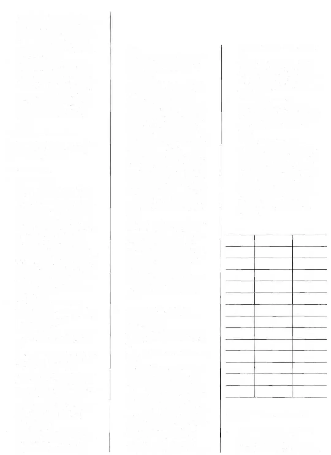
The following chart shows which
LED should turn on for each
combination of power-supply
connections:
-LEAD
3
3
3
3
2
2
2
2
1
1
1
symbol
symbol
symbol
+ LEAD
4
S
6
7
4
5
6
7
4
5
6
6
5
7
LED
1
2
4
S
15
30
60
125
250
500
1000
P
M
flash symbol
Troubleshooting steps for specific
problems:
I. Shutter won't release, no LEDs
Battery voltage to circuit
Check for 3V between ground
and the red wires (+), Fig. 21. No

 Loading...