Resistance, aperture-value resistor:
5.9K ± 10 ohms at f/8
Release point. 1st curtain: The 1st cur-
tain should release when the mirror is
I - 3mm from the porous-plastic strip
at the top front of the mirror box.
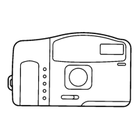
Timing, sprocket hook: The clearance
between the edge of the mirror-charge
lever and the sprocket hook should be
0 - 0.2mm with the wind lever held
fully advanced. Fig. I 3.
Wind-completion switch, space gap:
0.2 - 0.4mm
Release magnet: The space gap
between the release-magnet armature
and the release lever should be 0.1 -
0.3mm, Fig. 5. Adjust by shifting the
release magnet.
Counter gear: When the counter-
actuator lever is parallel to the ends of
the camera body, the pie-shaped open-
ing in the counter gear should face the
rewind end of the body. Fig. 15.
Sprocket: Turn the sprocket toward
the film aperture to take up the back-
lash. The sprocket should then be
within the range shown in Fig. 14 —
one pair of teeth pointing directly to
the back of the camera or within 30
degrees toward the take-up spool side.
ADJUSTMENT PROCEDURES
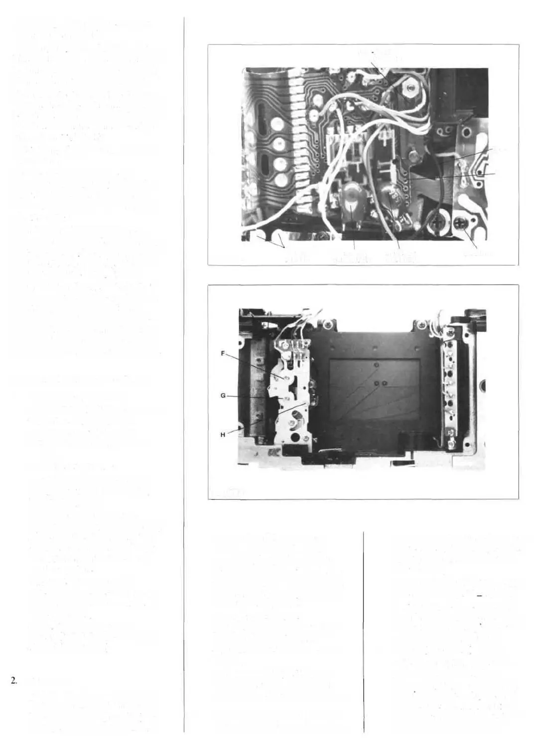
1. Aperture-control voltage
a. Connect a hook-up wire to the
aperture-voltage TP, Fig. 1.
b. Connect an oscilloscope
between the hook-up wire and
ground.
c. Set the lens to "A."
d. Set the scope to 2ms sweep
time. 20mv vertical deflection.
10:1 on the probe.
e. Release the shutter while
observing the diaphragm opening.
Make sure the diaphragm stops
down smaller than f/2.8. If not,
increase the light level to get a
smaller aperture.
f. Release the shutter while
observing the scope trace. Note
the peak-to-peak value of the sine
wave Adjust A,
Fig. I. for a value of 500 ±
lOOmv (turn the wiper clockwise
for a higher voltage).
Exposure
a. Set the program mode (lens at
"A," shutter speed at any setting).
b. Check at EV12 (ISO 100). The
aperture/shutter-speed combina-
LED FLEX
CONNECTOR
sws
SWH
FIGURE 3
HOT-SHOE
CONTACT APERTURE RELEASE
PIECES CAPACITOR CAPACITOR
3.
tion sould be f/4 and 1/250.
c. Adjust B , Fig. 1, for 0 EV
error or for a shutter speed of
3.9ms. Tolerance — 3.5 - 4.3ms.
Turn the wiper counterclockwise
for a longer exposure, clockwise
for a shorter exposure.
d. Check at EV8. The
aperture/shutter-speed combina-
tion should be 1/60 at f/2.
Shutter-speed tolerance — 12.2
-19.9ms.
e. Check at EV16. EVI0, and
EV6. The exposure should be
within ± 1.0EV at each light level.
Aperture-value (f-value) resistor
a. Unsolder the two yellow wires
4.
of the aperture-value resistor from
the flex PC board T100, Fig. 21.
Connect an ohmmeter between
the two wires.
b. Set the lens to f/8. The resist-
ance should be 5.9K + 10 ohms.
c. To adjust, remove the front-
plate/mirror-box assembly. Then
adjust the variable resistor at the
wind side of the front plate.
Shutter (1st curtain) release
a. Hold the bottom edge of the
mirror and push the release
button. Or, if power isn't being
supplied to the circuit, mechani-
cally release the mirror through
the cutout shown in Fig. 2 (push
the armature of the release
GROUND
FIGURE 4