7. Memory-lock switch. On front
plate, rewind side. Closes when
you push the ML button. The
LEDs turn on. and the auto expo-
sure remains locked for 10
seconds.
MAGNET LOCATIONS AND
FUNCTIONS
1. Release magnet. Hybrid magnet
at bottom of mirror box. Fig. 5.
I'hi- release magnet separates
when the release capacitor
discharges through its coil to
release the mirror.
2. Aperture magnet. Hybrid magnet
at wind-lever side of front plate.
The aperture magnet separates
when the aperture capacitor
discharges through its coil to latch
the movement of the aperture-
control lever and stop the
diaphragm.
3. Shutter magnet. Electromagnet in
shutter block, Fig. 21. Energized
when the release switch closes to
hold the 2nd curtain.
BASIC OPERATION
Note: The circuit operation is nearly
the same as that in the Super Program
and Program Plus. However, since the
P3 uses an LED display, the clock
only turns on when you push the
release button part way.
1. The circuit uses two ICs on the
underside of PC board T100:
ICI. Timing/control IC on the
rewind side. Fig. 6. ICI has the
built-in oscillator and supplies the
clock signal.
IC2. Interface and decoder/driver
on the wind side. Fig. 6. 1C2
switches the control transistors
and drives the LEDs.
2. Turning on the main switch
supplies battery voltage to the cir-
cuit. When you push the release
button part way, SWS closes.
Now ICI supplies the clock and
SV signals to IC2.
3. IC2 receives the mode and TV
information as digital signals from
the shutter-speed PC board. The
BV and AV signals are analog
values input to IC2. When IC2
receives the SWS and clock sig-
nals, it turns on the LEDs accord-
ing to the mode and exposure
inputs.
4. When you fully depress the
release button, the release switch
SWR closes. ICI then checks the
timing switch in the shutter block.
If the timing switch is closed —
and the wind-completion switch
is open — ICI supplies the
release signal to IC2. If the self-
timer switch is closed. IC I delays
the release signal for 12 seconds.
5. When IC2 receives the release
signal from ICI, it turns on the
release transistor. Fig. 16. The
release capacitor, Fig. 3. dis-
charges through the coil of the
release magnet. The release
magnet separates, releasing the
mirror.
6. As the diaphragm closes, the
7.
optical encoder supplies the feed-
back signal to IC2. The count
from the optical encoder is com-
pared to the count stored in ICI
memory. When the counts are
equal. IC2 stops the diaphragm
by turning on the aperture transis-
tor. Fig. 16. The aperture capaci-
tor then discharges through the
coil of the aperture magnet. The
aperture magnet separates, slop-
ping the aperture-control lever
Closing the release switch SWR
also energizes the shutter magnet
in the shutter block. IC2 turns on
the shutter transistor, Fig. 16, to
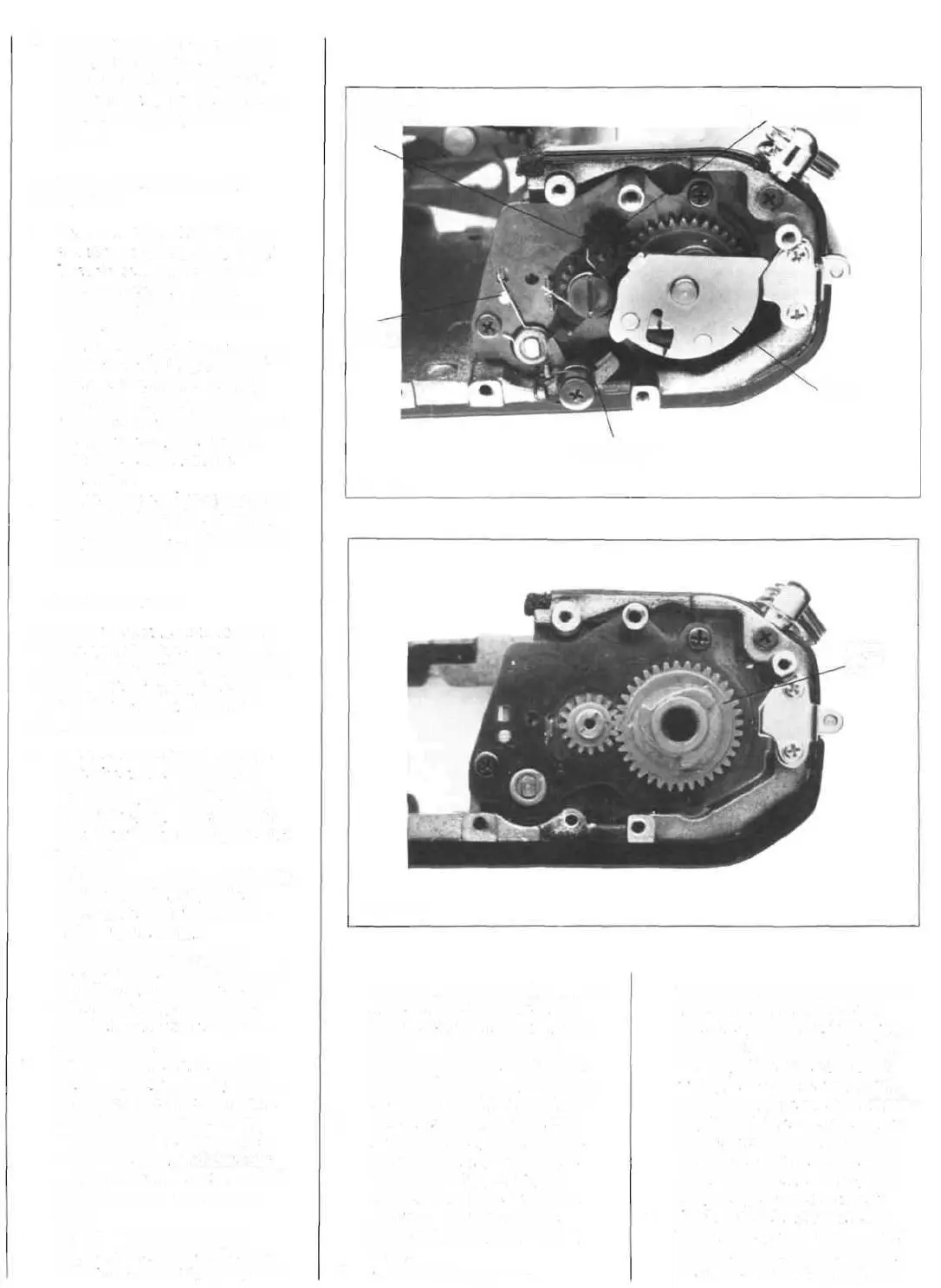
WIND
SHAFT
COUNTER GEAR C87
COUNTER-
ACTUATOR
LEVER
C96
SILENT
SPRING
RESTITUTION
LEVER C19
FIGURE 9
MAIN
GEAR
C30
FIGURE 10

 Loading...