voltage — battery box or wiring.
Main switch
With the main switch in the on
position, check for 3V at the
main-switch IP, Tig. 17. No vol-
tage poor contact in the main
switch or poor solder between the
main-switch flex and PC board
T100. Fig. 17. Or short between
the main-switch connections. Fig.
17. and close SWS. If the LEDs
then turn on, the problem is poor
contact in the main switch.
Ground to shutter-speed PC
board
Check for a loose ground screw,
Fig. 3.
Oscillator
Close SWS and check for the sine
wave at cither lead of the crystal.
Fig. I. No signal — poor solder
to crystal, crystal defective, or
1CI defective.
Clock
Close SWS and check for the
clock signal at the clock TP, Fig.
21. No signal IC" I defective.
!. Shutter won't release, LEDs
operate
Release switch SWR
Check at the SWR TP. Fig. 3.
The TP should connect to ground
with the release switch closed. Or
short the SWR TP to ground. If
the shutter then releases, the prob-
lem is poor contact in the release
switch or poor solder between the
shutter-speed flex. Fig. 16, and
PC board 1100.
Release magnet, release capacitor
Check if the LEDs turn off when
you close the release switch and
won't again turn on until you turn
the main switch off and then on.
Short the black lead of the release
magnet, Fig. 21, to ground. If the
shutter then releases, the release
magnet and the release capacitor
arc o.k. If the shutter doesn't
release, check the release magnet
between the red and black leads.
Fig. 21. Approximate coil resist-
ance — 12 ohms. Also check for
a dirty release-magnet interface.
You can check the release capaci-
tor. Fig. 3. by substituting a 47
microfarad capacitor.
Wind-completion switch
With the shutter cocked, check
the voltage at the orange wind-
completion-switch wire, Fig. 21.
The voltage should be high. If
you measure 0V, the wind-
completion switch isn't opening
or the orange wire is pinched.
Timing switch
With the shutter cocked, check
continuity between the white wire
(rewind side of PC board TI00)
and ground. You should measure
direct continuity. If not, check the
liming switch, Fig. 21. for poor
contact.
3. LEDs won't turn on when you
push the release button part way,
but do turn on when you release
the shutter
SWS
Check by shorting the SWS TP.
Fig. 21, to ground. If the LEDs
then turn on, the problem is poor
contact in SWS, Fig. 1, or poor
solder between the shutter-speed
flex and PC board T100, Fig. 16.
4. Diaphragm always stops down
fully on program mode
Aperture magnet, aperture-
magnei capacitor
Cock the shutter and short the
gray lead of the aperture magnet.
Fig. 21. to ground. You should
hear a click as the aperture
magnet separates. When you then
release the shutter, the diaphragm
should remain fully open. No
click — check the aperture-
magnet coil between the gray and
pink wires. Fig. 21. Approximate
coil resistance — 16 ohms. You
can check the aperture capacitor.
Fig. 3. by substituting a 47 micro-
farad capacitor.
Optical encoder
See, "Circuit Tests" — #1.
A/M switch
Check the LED display with the
lens at "A." Ifthe"P"LED
doesn't turn on, the problem may
be poor contact between the lens
and the A/M contact at the front
of the lens mount. Check the cir-
cuit by shorting the green A/M
wire, Fig. 21, to ground. If the
circuit is o.k.. the "P" LED will
turn on. Still no "P" LED — IC2
defective.
Note: If all tests check o.k.. but the
diaphragm still stops down fully, the
problem mav be an open aperture-
magnet transistor or a defective IC2,
Fig. 16. Replace PC board T100.
5. Shutter delivers fastest speed only
Shutter magnet
Short the brown shutter wire. Fig.
21, to ground and release the
shutter. The shutter should stay
open. If not. the shutter magnet is
open or dirty.
PC board T100
Check at the brown magnet wire.
Fig. 21, as you release the shutter.
The brown wire should switch
low when the release switch
closes. If not. the shutter-magnet
transistor or IC2 may be defec-
tive. Fig. 16.
6. LED always shows "1000"
(flickering), diaphragm stops
down fully on program mode
F-value (aperture) resistor
Check the resistance between the
two yellow wires. Fig. 21. At f/8.
you should measure 5.9K.
OTHER COMMENTS. PART
NUMBERS
1. The flex circuit is supplied only as
a complete unit including the
photocell board. New-style flex
PC board T100-01.
2. The LED block is supplied separ-
ately- See. "Revised Sections" #3.
3. The main-switch block is supplied
separately — 1200.
4. The Seiko shutter block is supp-
lied only as a complete unit —
O-E000."
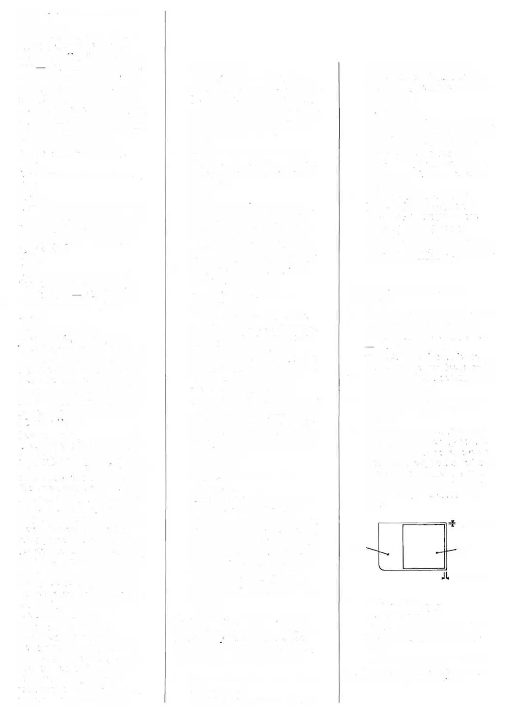
5. The spool-film sheet behind the
take-up spool is held by double-
sided tape. If you do remove the
spool-film sheet, it's best to install
a new part on reassembly. The
drawing here shows the position
for installing a new spool-film
sheet.
0.1 - 0.3 mm
A63
0.2 - 0.5 mm
6. Other part numbers:
- top cover — A300
- diaphragm-control block (aper-
ture magnet, optical encoder) —
G100
- release-magnet block — S100
Note: Part numbers for the transport
arc shown on the illustrations.
A64
 Loading...