H-System – Isolated Barriers and Termination Boards
Product Specifications
2023-03
9
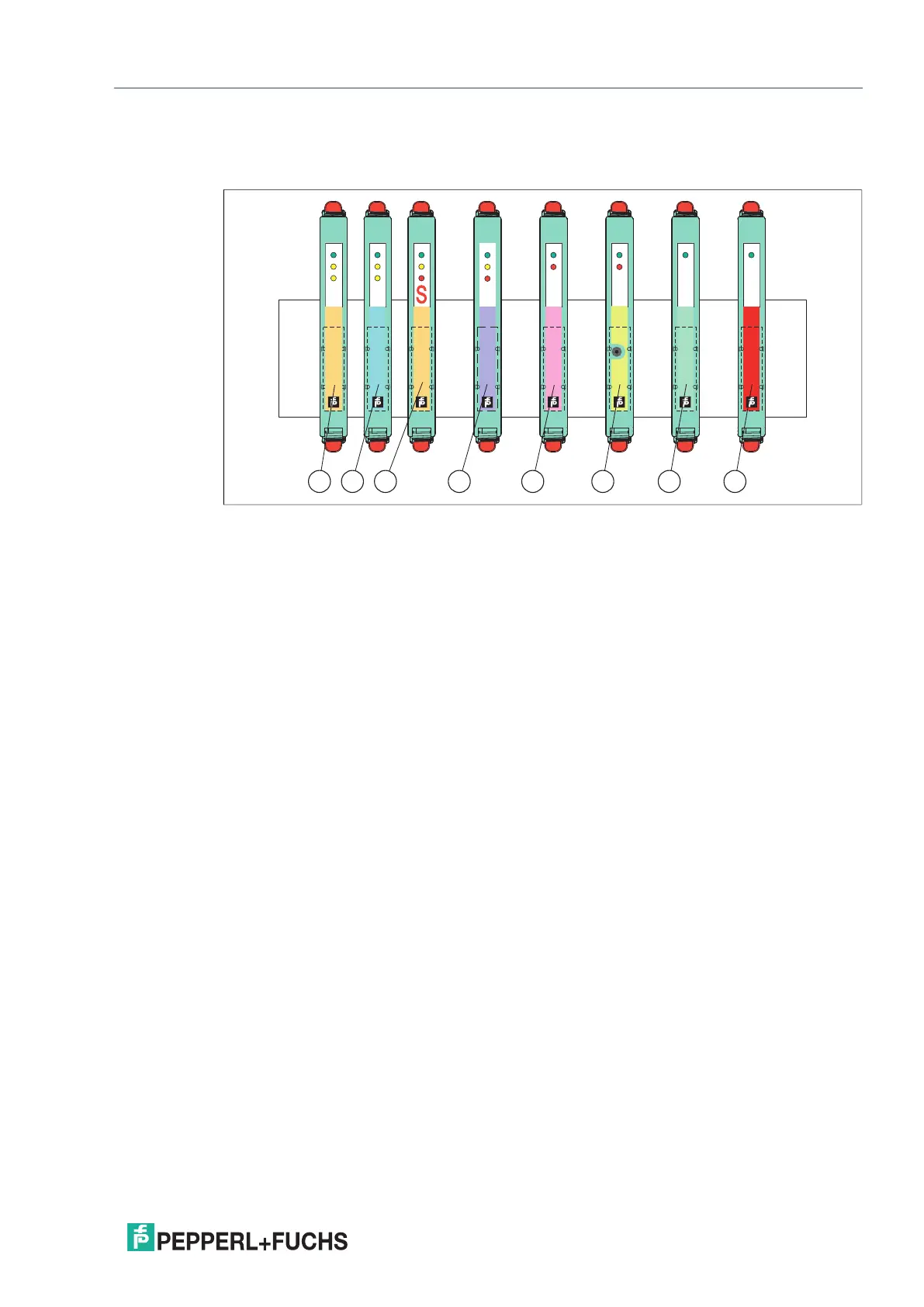
2.2.1 Color Coding of the Isolated Barriers
The color coding of the devices has the following meaning:
Figure 2.3 Color identification of devices
1 Digital input – switch amplifier with relay output
2 Digital input – switch amplifier with transistor output
3 Digital input – switch amplifier with transistor output and active voltage output for safety
sensors SN, S1N
4 Digital output – solenoid driver, relay module
5 Analog input – transmitter power supply, converter, repeater
6 Temperature input – temperature converter
7 Analog output – current driver
8 Universal input/output – universal barrier
PWR
HiC
2025
ES
PWR
HiC
2851
1 ch
Digital
Input
STATUS
FAULT
PWR
HiC
2822
2 ch
Digital
Input
CH1
PWR
HiC
2842
2 ch
Digital
Input
CH1
CH2CH2
STATUS/
FAULT
STATUS/
FAULT
PWR
HiC
2441
1 ch
Analog
Input
1 ch
Universal
Input/
Output
PWR
HiC
2883
1 ch
Digital
Output
STATUS FAULT
PWR
HiC
2031
HC
1 ch
Analog
Output
PWR
FAULT
FAULT
PROG
1 ch
Temp.
Input
HiC
2081
21 3 4 5 6 7 8
 Loading...