2023-03
18
H-System – Isolated Barriers and Termination Boards
Product Specifications
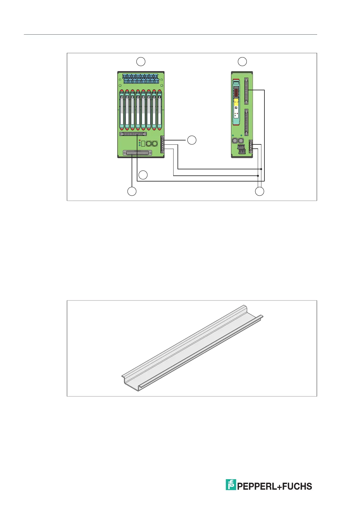
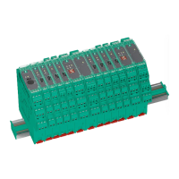
Figure 2.20 H-System topology
2.3.4 DIN Mounting Rail, on the User Side
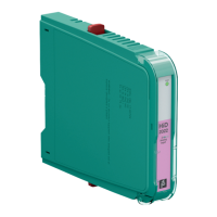
The termination boards are mounted on a 35 mm DIN mounting rail according to EN 60715.
Figure 2.21 Example: DIN mounting rail (35 mm x 7.5 mm)
1 Termination board
2 HART Communication Board
3 Connection power supply I and II (redundant)
4 Connection control side
5 Connection HART communication
6 Connection fault indication output
PWR
HART TXFAULT
OFFON
HiD
Mux
2700
Hart
1 2
4 3
6
5