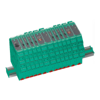
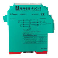
H-System – Isolated Barriers and Termination Boards
Technical Specifications
2023-03
39
Mechanical Data
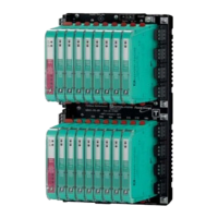
Mounting
• Termination boards: Snap-on 35 mm DIN mounting rail according to EN 60715.
Can be mounted horizontally or vertically.
• Isolated barriers: mounting on termination board via Quick Lok Bar
Housing Material
• Termination boards:
• Polycarbonate (PC)
• Polycarbonate (PC), glass fiber reinforced
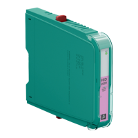
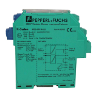
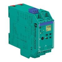
• Isolated barriers: Polycarbonate (PC)
Dimensions
• Dimension drawings please refer to Dimensions section.
Degree of Protection
• Termination boards:
• without isolated barriers IP00 according to EN 60529
• with isolated barriers plugged IP20 according to EN 60529
• Isolated barriers: IP20 according to EN 60529
Connection to Termination Board
• Field side:
• Screw terminals: 0.25 to 1.5 mm
2
(24 ... 12 AWG)
Observe the tightening torque of the terminal screws. The tightening torque
is 0.5 Nm to 0.6 Nm.
• Pluggable screw terminals: 0.25 to 2.5 mm
2
(24 ... 12 AWG)
Observe the tightening torque of the terminal screws. The tightening torque
is 0.5 Nm to 0.6 Nm.
• Spring terminals: 0.25 to 1.5 mm
2
(24 ... 12 AWG)
• Power supply and fault indication output:
• Screw terminals: 0.25 to 1.5 mm
2
(24 ... 12 AWG)
Observe the tightening torque of the terminal screws. The tightening torque is
0.5 Nm to 0.6 Nm.
• Spring terminals: 0.25 to 1.5 mm
2
(24 ... 12 AWG)
• Control side:
• Screw terminals: 0.25 to 1.5 mm
2
(24 ... 12 AWG)
Observe the tightening torque of the terminal screws. The tightening torque is
0.5 Nm to 0.6 Nm.
• Spring terminals: 0.25 to 1.5 mm
2
(24 ... 12 AWG)
• Control-system specific connector: Sub-D connector
Fire Protection Class
• Housing: V2 according to UL 94 standard. Unless stated otherwise all details relate to the
reference conditions.