Do you have a question about the Pepperl+Fuchs KFD2-WAC2-Ex1.D and is the answer not in the manual?
Details on conductor cross section, ferrules, copper conductors, terminals, insulation, and tightening torque.
Guidelines for intrinsically safe circuits, separation distances, and explosion protection verification.
Specifies requirements for surrounding enclosures and degree of protection IP54.
This document outlines the operational and safety guidelines for a Strain Gauge Converter, model KFD2-WAC2-Ex1.D, manufactured by Pepperl+Fuchs Group. It serves as a comprehensive guide for personnel involved in the planning, assembly, commissioning, operation, maintenance, and dismounting of the device, emphasizing the importance of proper training and adherence to all applicable laws, standards, and directives.
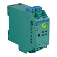
The Strain Gauge Converter is primarily designed for use in control and instrumentation technology (C&I technology). Its core function is the galvanic isolation of standard signals, such as 20 mA and 10 V, or alternatively, for adapting or standardizing various signals. A key feature of this device is its incorporation of intrinsically safe circuits, which are specifically designed for operating intrinsically safe field devices within hazardous areas. This makes it suitable for applications involving strain gauges, load cells, and resistance measuring bridges, where safety in potentially explosive atmospheres is paramount. The device is classified as an associated apparatus according to IEC/EN 60079-11 and is suitable for hazardous areas of Class I, Division 2, or Class I, Zone 2. It is intended for stationary use and must be operated only within its specified ambient and operating conditions.
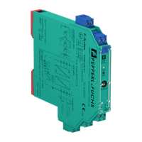
For installation, the device is designed for mounting on a 35 mm DIN mounting rail, compliant with EN 60715. It requires protection against mechanical hazards, typically achieved by mounting it within a surrounding enclosure that can only be opened with a tool. The device has an IP20 degree of protection according to IEC/EN 60529, necessitating installation in a controlled environment with a pollution degree of 2 or better, as per IEC/EN 60664-1. If used in environments with higher pollution degrees, additional protection for the device is required. It is crucial not to mount the device in dust hazardous areas. The operational environment must also adhere to an overvoltage category II or better, as specified by IEC/EN 60664-1. The device must be powered by a safety extra-low voltage (SELV) or protective extra-low voltage (PELV) supply. If utilizing a Power Rail, it must be supplied exclusively via corresponding power feed modules or power supplies, never through isolators. All installation procedures must comply with IEC/EN 60079-14. For safety-related applications, specific functional safety requirements must be observed.
Regarding cabling and connections, it is essential to use only copper conductors with appropriate core cross-sections. Stranded conductors require crimped wire end ferrules. Each terminal should accommodate only one conductor, and the insulation must extend fully to the terminal. The tightening torque for terminal screws must be observed. For voltages exceeding 50 V AC or 120 V DC, the voltage must be switched off before connecting or disconnecting the device. Cables and connection lines must have a temperature range suitable for the application. A critical safety instruction states that if circuits with Ex i type of protection are operated with non-intrinsically safe circuits, they can no longer be used as Ex i circuits. When connecting intrinsically safe field devices to intrinsically safe circuits of associated apparatus, the respective peak values of both the field device and the associated apparatus must be considered for explosion protection, in accordance with IEC/EN 60079-14 and IEC/EN 60079-25. Intrinsically safe circuits of associated apparatus can extend into hazardous areas, but strict adherence to separation distances from non-intrinsically safe circuits and between adjacent intrinsically safe circuits, as per IEC/EN 60079-14, is mandatory.
For equipment protection level Gc, the device must be installed and operated within surrounding enclosures that meet IEC/EN 60079-0 requirements and have an IP54 degree of protection according to IEC/EN 60529. Connection or disconnection of energized non-intrinsically safe circuits is only permissible in the absence of a potentially explosive atmosphere. Transient protection must be provided, ensuring that the peak value of the transient protection does not exceed 140% of the rated voltage.
Maintenance and repair guidelines emphasize that for safety-related applications, functional safety requirements must be observed, including planning appropriate intervals for proof tests in low demand mode. For voltages above 50 V AC or 120 V DC, the power must be switched off before connecting or disconnecting the device. It is strictly prohibited to use damaged or polluted devices, and no repairs, modifications, or manipulations of the device are allowed. In case of a defect, the device must always be replaced with an original unit. For equipment protection level Gc, connection or disconnection of energized non-intrinsically safe circuits, as well as the use of operating elements and the programming socket, are only permitted in the absence of a potentially explosive atmosphere.
For delivery, transport, and disposal, it is essential to inspect the packaging and contents for damage upon receipt and verify that all items match the order. The device should always be stored and transported in its original packaging, in a clean and dry environment, considering the permitted ambient conditions specified in the datasheet. The device, its built-in components, packaging, and any contained batteries must be disposed of in compliance with applicable laws and guidelines of the respective country. This comprehensive approach ensures the safe and effective use of the Strain Gauge Converter throughout its lifecycle.
| Type | Media Converter |
|---|---|
| Protection Class | IP20 |
| Temperature Range | -20 °C to +60 °C |
| Indicators/settings | LED indicators for power and status |
| Directive conformity/Certification | ATEX, IECEx |