EasyManua.ls Logo

PERFECTPASS MasterCraft 2007 - User Manual

PERFECTPASS MasterCraft 2007
7 pages
Print Icon
To Next Page IconTo Next Page
Loading...
MasterCraft 2007
Troubleshooting
(Electronic Throttle Engines)
System Not Controlling/Surging in both RPM & Speed Mode
You can quickly perform a “Control Test” to confirm whether PerfectPass has proper control of
the ECM. This test is on Page 3 and can be done on a “fake lake” or in the water.
The PerfectPass “Drive by Wire” (DBW) system for new electronic throttle engines
results in a simplified and enhanced version of PerfectPass. From the drivers seat,
PerfectPass operation is virtually identical to the present mechanical systems.
PerfectPass is now comprised of just four main parts:
1. DBW Master Control Module
2. DBW Plug & Play Engine Wiring Harness
3. Plug & Play Display Harness
4. In-Dash Display
5. ALDL Plug
On 2007 MCX and RPT, an “ALDL” ground plug is
required. On the 2006 6.0L and 8.lL, a re-flash of the
ECM is required.
Engine Display
Harness Harness
How it Operates:
The ECM of an electronic throttle engine allows an external device such as PerfectPass
to control the engine rpm using the throttle servo motor when all control signals are valid
and manual throttle lever position exceeds the rpm level request of PerfectPass.
Just three individual wires in the PerfectPass DBW wiring harness connect the speed
control to the engine ECM.
1. The Request Line from PerfectPass requests the ECM to allow PerfectPass to take
control.
2. The Status Line from the ECM indicates PerfectPass now has control of the engine.
The Status Line is the signal that confirms engagement (beeper) and system control
and
must be operational for system to engage & control properly.
3. The VGOV Line establishes the engine RPM level as set by PerfectPass.
Problems with PerfectPass should be rare given the few components that now make up
the system. Most troubleshooting will simply involve voltage/continuity testing on the
PerfectPass engine harness.
PerfectPass Control Systems (902) 468-2150 Page 1
Question and Answer IconNeed help?

Do you have a question about the PERFECTPASS MasterCraft 2007 and is the answer not in the manual?

Summary

How it Operates

Wiring Identification

Testing (Control Test)

Voltage Test

Other Measurements

Trouble Shooting DBW

Control Settings

CS Control

Controls engagement in paddle wheel speed-based modes like wakeboard. Adjusts sensitivity.

CR Control

Controls engagement in RPM-based modes like slalom. Rarely requires adjustment.

Software Adjustments

System Reset

Resets the entire system to original factory values. Initiated via key and button combination.

System Configuration

WakeboardPro vs. DigitalPro

Switch between WakeboardPro and DigitalPro modes by performing a system reset.

Engine Selection

Selects the correct engine type (e.g., 5.7L, Big Block) for optimal system performance.

Overview

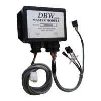
The provided document describes the MasterCraft 2007 PerfectPass "Drive by Wire" (DBW) system, an electronic throttle control system designed for new electronic throttle engines. This system simplifies and enhances the functionality of PerfectPass, offering operation virtually identical to previous mechanical systems from the driver's seat.

Function Description:

The PerfectPass DBW system allows an external device to control the engine RPM by manipulating the throttle servo motor. This control is active when all control signals are valid and the manual throttle lever position exceeds the RPM level requested by PerfectPass. The system is designed to maintain a set speed or RPM, offering modes like WakeboardPro and DigitalPro. It integrates with the engine's Electronic Control Module (ECM) through a dedicated wiring harness.

System Components:

The PerfectPass DBW system consists of four main parts:

  1. DBW Master Control Module: The central processing unit for the system.
  2. DBW Plug & Play Engine Wiring Harness: Connects the Master Control Module to the engine's ECM.
  3. Plug & Play Display Harness: Connects the Master Control Module to the in-dash display.
  4. In-Dash Display: Provides user interface and feedback.
  5. ALDL Plug: Required for 2007 MCX and RPT engines; for 2006 6.0L and 8.1L engines, an ECM re-flash is needed.

Key Wiring Connections and Signals:

The system communicates with the engine ECM via three critical wires in the PerfectPass DBW wiring harness:

  1. Request Line (RQST): From PerfectPass to the ECM, requesting control.
  2. Status Line (STAT): From the ECM to PerfectPass, indicating that PerfectPass has control of the engine. This signal confirms engagement (accompanied by a beeper) and is crucial for proper system operation.
  3. VGOV Line: Establishes the engine RPM level as set by PerfectPass.

The wiring identification table provides detailed connections:

  • STAT (Orange wire): Connects to pin 1 of the 9-Pin MATE-N-LOK connector, pin 1 of the 14-Pin AMPSEAL, connector D at the engine, and ECM J1-55.
  • VGOV (Blue wire): Connects to pin 2 of the 9-Pin MATE-N-LOK, pin 10 of the 14-Pin AMPSEAL, connector E at the engine, and ECM J3-57.
  • RQST (Brown wire): Connects to pin 3 of the 9-Pin MATE-N-LOK, pin 12 of the 14-Pin AMPSEAL, connector C at the engine, and ECM J1-30/J1-45.
  • Ground (Black wire): Connects to pin 4 of the 9-Pin MATE-N-LOK, pin 14 of the 14-Pin AMPSEAL, and connector H at the engine.
  • RPM (White wire): Connects to pin 5 of the 9-Pin MATE-N-LOK, pin 9 of the 14-Pin AMPSEAL, connector B at the engine, and ECM J1-24/J1-25.
  • Speed (Green wire): Connects to pin 6 of the 9-Pin MATE-N-LOK, pin 8 of the 14-Pin AMPSEAL.
  • 12 Volts (Red wire): Connects to pin 7 of the 9-Pin MATE-N-LOK, pin 4 of the 14-Pin AMPSEAL.

Usage Features:

  • Control Test: A diagnostic test to confirm proper control of the ECM. This can be performed on a "fake lake" or in the water. To enter, press Menu & UP Keys, scroll to "Device Test," then "Servo/Control Test." During the test, the system requests control and maintains a constant 1-volt level. An "S" on the display indicates proper system function.
  • RPM Control: In Control Test mode, with the engine ON and gearshift in neutral, advancing the throttle handle to 1800 RPM should result in the engine holding at approximately 1730 RPM (with potential surges of about 100 RPM).
  • Speedometer Adjustment: For Wakeboard mode, if the actual speed differs from the digital speedometer reading, the "SPEEDOMETER ADJUST" setting can be accessed via the Menu Key to calibrate the speed.
  • Screen Contrast Adjustment: Press Menu & UP Keys together, then UP Key a couple of times to adjust.
  • Engine Selection: During initial setup or system reset, the user is prompted to select the engine type (e.g., 5.7 litre, Big Block 6L or 8.1L). Incorrect selection can cause unsettled control in RPM mode.
  • WakeboardPro/DigitalPro Switching: The Master Module hardware is identical for both systems; the difference lies in their initialization. A system reset allows switching between these modes.

Maintenance and Troubleshooting Features:

The document provides extensive troubleshooting guidance for common issues:

Problems with Controlling / Not Controlling:

  • RQST Line Open: PerfectPass never takes control; engine controlled only by manual throttle.
  • VGOV Line Open: With PerfectPass control ON, engine stays at idle regardless of manual throttle position. With PerfectPass OFF, manual throttle works normally.
  • STAT Line Open: Engine operates normally with PerfectPass ON, but RPMs are limited slightly above the set point, no proper control, and speed is 1-2 mph above set point. No engagement beep or underline characters appear.
  • PerfectPass Does Not Engage (No "S" during control test): Check "ALDL" ground plug connection.
  • System Surges (during operation and control test): Indicates a poor ground connection. Check and tighten all wires at the ground bar.

Voltage Test (Control Test Mode):

Measurements are taken with the system ON and "R" on screen, using test tee connectors or small pins at the 14-pin engine connector or 9-pin MAT-N-LOK connector.

  • RQST Line: Should measure less than 1 volt (0-1V) (engine running or not). When OFF, should measure more than 4.5 volts.
  • VGOV Line: Should measure about 1 volt (0.8-1.2V) (engine running or not).
  • STAT Line: Will be 10+ volts when "S" is not on display. When engaged and working properly, this pin at the ECM is grounded, and voltage will be less than 1 volt (engine must be running for STAT measurement).

Other Measurements (Control OFF, "R" not on screen):

  • RQST Line: ~4.5 V
  • VGOV Line: ~4 V+
  • STAT Line: ~10 V+

General Troubleshooting:

  • System surges in all modes: Check main ground wire and perform open circuit voltage tests on VGOV, STAT, and RQST lines.
  • System does not engage: Perform a CONTROL TEST. If it engages, check adjustable parameters (KDW, NN, CS/CR). If not, perform Open Circuit Tests. Ensure RPM reading is on screen.
  • No speed reading on PerfectPass Display: Check paddle wheel signal on the green wire at the Master Module (0V/12V when wheel turns slowly, ~5V when spun quickly). If voltage is good, perform a "System Reset." If the MasterCraft speedometer isn't reading, correct it first.
  • No RPM reading on PerfectPass display: Check RPM signal wire at the Amp Seal connector. Should be ~9V with engine off, and a normal tach pulse signal with engine running. If no signal, check the pin at the ECM.
  • PerfectPass screen not active/no data: Check 12+ volts on the red power wire to the Master Module. Check screen contrast.
  • Button on PerfectPass Display does not work: Inspect brass pins on the connector for alignment. If problem persists, display may need repair.
  • Sluggish/surging in Wakeboard/Trick mode: Inspect paddle wheel. Adjust KDW (firmness of control, 80-200 for heavily loaded boats) and NNW (paddle filter factor, 80-180).
  • Boat accelerates past set speed in Wakeboard Mode: Lower the "CS" value in "Control Settings."

Software Adjustments:

  • System Reset: To restore factory values, press & hold ON/OFF & MENU Keys together while turning the key ON. Continue holding until "[ System Reset ^ = Yes ]" appears, then answer the prompts.

Control Settings (CR / CS):

These adjustable engagement values fine-tune performance, especially after prop changes, ballast loads, or extreme elevations.

  • CS (Control Speed): Controls engagement in paddle wheel speed-based modes (e.g., wakeboard). Factory setting is 750 (range 735-900). Too low, system may not engage or disengage. Too high, may overshoot set speed.
  • CR (Control RPM): Controls engagement of RPM-based modes (e.g., slalom). Factory setting is 1940 (range 1900-2100). Rarely requires adjustment.

The document emphasizes that problems with PerfectPass should be rare due to the system's few components, with most troubleshooting involving voltage/continuity testing on the PerfectPass engine harness.

PERFECTPASS MasterCraft 2007 Specifications

General IconGeneral
BrandPERFECTPASS
ModelMasterCraft 2007
CategoryController
LanguageEnglish