6. For best results, use only hydraulic
uidwitharatingofSAE20forrells.
Checkuidlevelwithpumpinfullydown
position.
7. Change the hydraulic oil at least once
every three years:
a. SetPump(1)atonalevelsurface.
b. Remove the Fill Screw (A). The O-
ring (B) should come off with it.
c. Tip the pump to allow the old hy-
draulic oil to drain out of the housing
completely, and dispose of the old
hydraulic oil in accordance with local
regulations.
d. With the Pump upright, completely
llthehousingwithahighquality
hydraulic oil (not included) until the
oil just begins to run out of the oil
llhole.BeVERYCAREFULnotto
allow dirt or foreign matter into the
system.
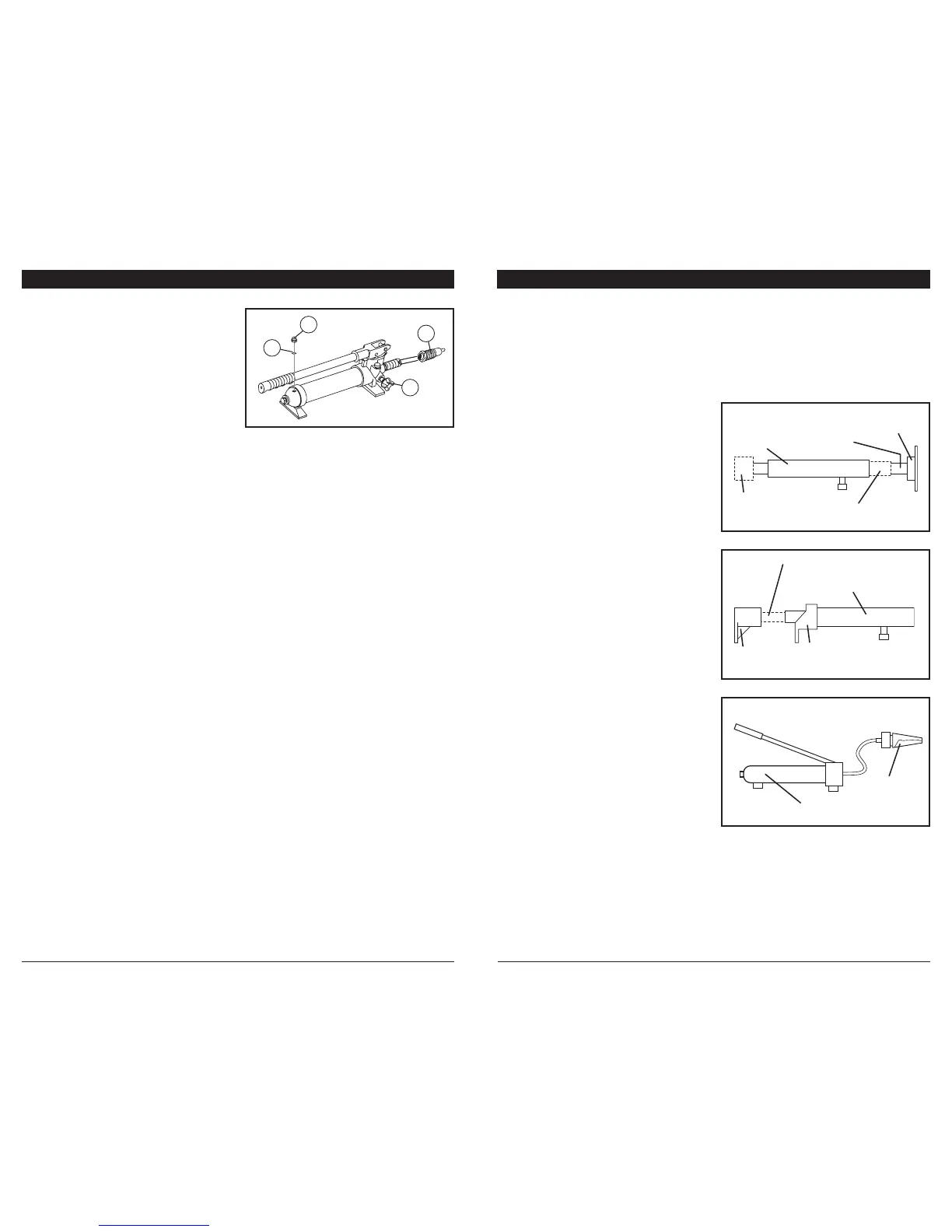
CARE & MAINTENANCE
A
B
C
D
Fig. 5
e. Make sure the O-ring (B) is still in
place around the Fill Screw (A) and
thread the Fill Screw into the Pump
securely. Do not use thread seal
tape.
f. Firmly close the Release Valve (C) by
turning it clockwise.
g. Clean with a clean cloth using a
detergent or mild solvent.
Ram Setup:
Note: When positioning the Ram (3) use a
smaller attachment on the side that
is to be bent instead of the stationary
side. If the stationary side is in dan-
ger of being bent or damaged, place
a block of wood or other material
behind the Flat Base (9) to distribute
pressure over a greater area.
1. Clean the end of the Hose and the inlet
on the Ram (3). Unscrew and save the
End Plugs located on the end of the hose
and Ram (3).
2. Attach the Hose to the Ram.
3. Assemble attachments as shown in
gure1and2.
Note: If using the Plunger Toe and Ram
Toe, thread the Ram Toe onto the
Ram completely and align the
Plunger Toe to it.
Spreader Wedge Setup:
The Spreader Wedge (2) is used when the
Ram(3)istoolongtotbetweenthestation-
ary side and the damaged area.
1. Clean the end of the hose and the inlet on
the Spreader Wedge (2).
2. Unscrew and save the End Plugs located
on the end of the hose and Spreader
Wedge (2).
3. Attach the Hose to the Spreader Wedge
(2),asshowningure3.
SETUP INSTRUCTIONS
Note: The Flange Base and Flange Head must only be used together to prevent an off
center load.
Note: When positioning the Ram (3) use a smaller attachment on the side that is to be
bent instead of the stationary side. If the stationary side is in danger of being bent
or damaged, place a block of wood or other material behind the Flat Base (9) to
distribute pressure over a greater area.
Fig. 1
Fig. 2
Fig. 3
Ram (3)
Ram (3)
Spreader
Wedge (2)
Male
Connector (14)
Extension Bars (5-8)
as needed
Extension Bars (5-8)
as needed
Pump (1)
V-base (13) or
Flat Base (9)
Cap Head (15)
Rubber Head (16)
or Wedge Head (12)
Plunger
Toe (11)
Ram
Toe (10)