21
Component Voltage
Battery Cable
Connectors 50mV
Connections 0.0V
• Compare voltage readings in
Step 6 with above chart.
•
If any voltages read high, inspect
component and connection for
defects.
• If defects are found, service as
necessary.
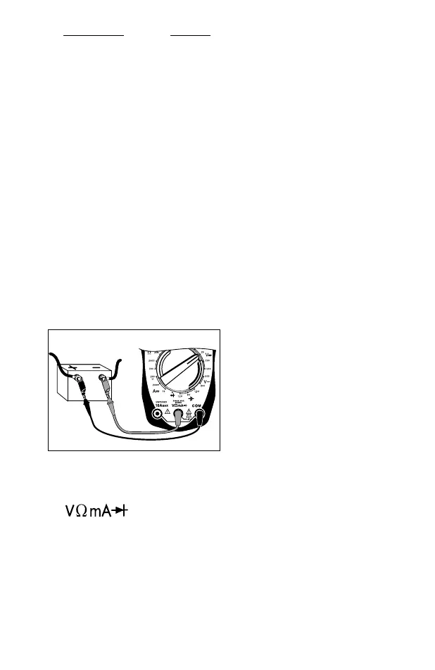
Fig. 21
Red
Black
7. Turn off all accessories and
view reading on display.
• Charging system is normal if
display reads 13.2 to 15.2 volts.
• If display voltage is not be-
tween 13.2 to 15.2 volts, then
proceed to Step 13.
8. Open throttle and Hold engine
speed (RPM) between 1800 and
2800 RPM.
Hold this speed through Step 11 -
Have an assistant help hold
speed.
9. View reading on display.
Voltage reading should not
change from Step 7 by more
than 0.5V.
10.Load the electrical system by
turning on the lights, wind-
shield wipers, and setting the
blower fan on high.
11.View reading on display.
Voltage should not drop down
below about 13.0V.
12.Shut off all accessories, re-
turn engine to curb idle and
shut off.
1. Insert BLACK test lead into
COM test lead jack.
2. Insert RED test lead into
test lead jack.
3. Turn multimeter rotary switch
to 20V DC range.
4. Connect RED test lead to posi-
tive (+) terminal of battery.
5.
Connect BLACK test lead to
negative (-) terminal of battery.
6. Start engine - Let idle.
Charging System Voltage Test
This test checks the charging sys-
tem to see if it charges the battery
and provides power to the rest of the
vehicles electrical systems (lights,
fan, radio etc).
Test Procedure (see Fig. 21):