8
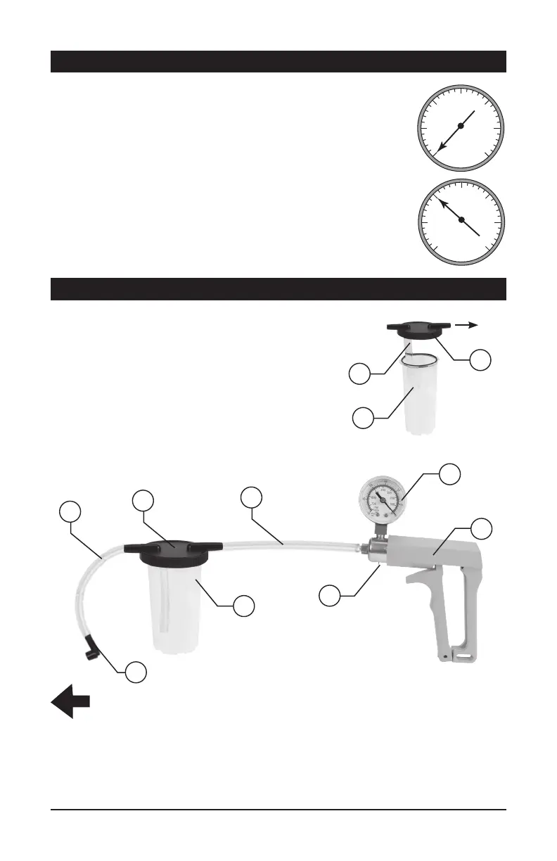
Figure A
TO WHEEL CALIPER
BLEEDER SCREW
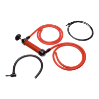
1. Attach a 3 in. Vacuum Hose (8) to the bottom of the
Jar Lid (4). (See Figure A.)
2. Attach a 24 in. Vacuum Hose (7) to the top of the Jar
Lid (4) marked “TO PUMP”. Then, attach the other
end of the 24 in. Vacuum Hose (7) to the Vacuum
Pump (1). (See Figure B.)
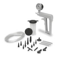
3. Press one of the small rubber jar gaskets from the kit
into the inner lip of the 4.5 ounce Reservoir Jar (6).
Add a touch of light oil to the gasket to insure the
gasket won’t get pinched and for a good seal. Twist
the Jar Lid (4) onto the Reservoir Jar (6), it’s about
1/8 turn, do not over tighten.
4
To Pump
8
4. Connect the other 24 in. Vacuum Hose (7) to the remaining port on the Jar Lid (4) and
then connect the other end to the Brake Bleeder Screw Adapter (12).
5. With your finger over the adapter opening squeeze the handle of the Vacuum Pump (1)
a few times to create a vacuum in its Reservoir Jar (6). Press the the Vacuum Release
Valve (3) to release the pressure.
6
Figure B
7
4
7
2
1
3
6
12
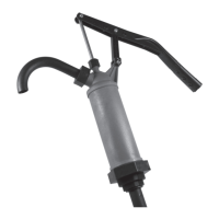
1. Attach the vacuum pump to the bottom port and apply vacuum,
approx. 10 in. of Hg.
• The needle should hold steady and not bleed off.
If it does not hold, unit is bad and should be replaced.
2.
Repeat the procedure after the engine has warmed to normal temp.
• As vacuum is applied it should bleed off to zero. If it
holds steady, unit is bad and should be replaced.
NOTE: These thermal switch are needed to provide good drive ability.
It limiting the entrance of exhaust gases until the engine is warmed
up. Depending on the vehicles make your thermal switch may have
more than two ports. You may have three or four ports, the end
function is the same. They control vacuum going to different
applications until the engine has warmed to normal operating temp.
Consult your service manual for the type used on your vehicle.
TESTING PROCEDURES CONT.
0
5
10
15
20
25
30
Hg Hg
Vacuum
Gauge
0
5
10
15
20
25
30
Hg Hg
Vacuum
Gauge
0
5
10
15
20
25
30
Hg Hg
Vacuum
Gauge
0
5
10
15
20
25
30
Hg Hg
Vacuum
Gauge
0
5
10
15
20
25
30
Hg Hg
Vacuum
Gauge
0
5
10
15
20
25
30
Hg Hg
Vacuum
Gauge
Nornal
Leaking Intake Valve Timing
Ignition Timing
Misre
Clogged Exhaust
0
5
10
15
20
25
30
Hg Hg
Vacuum
Gauge
Broken Valve Spring
0
5
10
15
20
25
30
Hg Hg
Vacuum
Gauge
0
5
10
15
20
25
30
Hg Hg
Vacuum
Gauge
0
5
10
15
20
25
30
Hg Hg
Vacuum
Gauge
Blown Head Gasket
Worn Valve Guides
Leaking Valve
0
5
10
15
20
25
30
Hg Hg
Vacuum
Gauge
0
5
10
15
20
25
30
Hg Hg
Vacuum
Gauge
Fuel mixture
Leaking Piston Ring
0
5
10
15
20
25
30
Hg Hg
Vacuum
Gauge
Vacuum Solenoid
0
5
10
15
20
25
30
Hg Hg
Vacuum
Gauge
0
5
10
15
20
25
30
Hg Hg
Vacuum
Gauge
0
5
10
15
20
25
30
Hg Hg
Vacuum
Gauge
BLEEDER PUMP ASSEMBLY
0
5
10
15
20
25
30
Hg Hg
Vacuum
Gauge
0
5
10
15
20
25
30
Hg Hg
Vacuum
Gauge
0
5
10
15
20
25
30
Hg Hg
Vacuum
Gauge
0
5
10
15
20
25
30
Hg Hg
Vacuum
Gauge
0
5
10
15
20
25
30
Hg Hg
Vacuum
Gauge
0
5
10
15
20
25
30
Hg Hg
Vacuum
Gauge
Nornal
Leaking Intake Valve Timing
Ignition Timing
Misre
Clogged Exhaust
0
5
10
15
20
25
30
Hg Hg
Vacuum
Gauge
Broken Valve Spring
0
5
10
15
20
25
30
Hg Hg
Vacuum
Gauge
0
5
10
15
20
25
30
Hg Hg
Vacuum
Gauge
0
5
10
15
20
25
30
Hg Hg
Vacuum
Gauge
Blown Head Gasket
Worn Valve Guides
Leaking Valve
0
5
10
15
20
25
30
Hg Hg
Vacuum
Gauge
0
5
10
15
20
25
30
Hg Hg
Vacuum
Gauge
Fuel mixture
Leaking Piston Ring
0
5
10
15
20
25
30
Hg Hg
Vacuum
Gauge
Vacuum Solenoid
0
5
10
15
20
25
30
Hg Hg
Vacuum
Gauge
0
5
10
15
20
25
30
Hg Hg
Vacuum
Gauge
0
5
10
15
20
25
30
Hg Hg
Vacuum
Gauge
 Loading...