Valve System Components
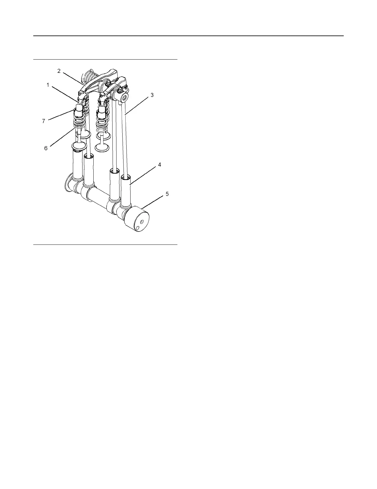
Illustration 15 g01924293
Valve system components
(1) Bridge
(2) Rocker arm
(3) Pushrod
(4) Lifter
(5) Camshaft
(6) Spring
(7) Valve
The valve system components control the flow of
inlet air into the cylinders during engine operation.
The valve system components also control the flow
of exhaust gases out of the cylinders during engine
operation.
The crankshaft gear drives the camshaft gear
through an idler gear. The camshaft (5) must be
timed to the crankshaft in order to get the correct
relation between the piston movement and the valve
movement.
The camshaft (5) has two camshaft lobes for each
cylinder. The lobes operate either a pair of inlet
valves or a pair of exhaust valves. As the camshaft
turns, lobes on the camshaft cause the lifter (4) to
move the pushrod (3) up and down.
The lifter (4) incorporates a hydraulic lash adjuster
which removes valve lash from the valve mechanism.
The lifter (4) uses engine lubricating oil to
compensate for wear of system components so that
no service adjustment of valve lash is needed.
The engine lubricating oil enters the lifter (4) through
a non-return valve. The engine lubricating oil
increases the length of the lifter (4) until all valve lash
is removed. If the engine is stationary for a prolonged
period the valve springs will cause the lifter (4) to
shorten so that when the engine is started engine
valve lash is present for the first few seconds.
After cranking restores oil pressure the lifter (4)
increases in length and removes the valve lash.
When load is removed from a lifter (4) during service
work by the removal of the rocker shaft the lifter (4)
increases in length to the maximum extent. Refer to
Systems Operation, Testing and Adjusting, “Position
the Valve Mechanism Before Maintenance
Procedures” for the correct procedure.
During reassembly of the rocker shaft the engine
must be put into a safe position to avoid engine
damage. After load is imposed on the lifters by
reassembling the rocker assembly, the engine must
be left in safe position for a safe period until the lifters
have reduced to the correct length. Refer to
Disassembly and Assembly, “Rocker Shaft and
Pushrod - Install” for the correct procedure.
Upward movement of the pushrod against rocker arm
(2) results in a downward movement that acts on the
valve bridge (1). This action opens a pair of valves
(7) which compresses the valve springs (6). When
the camshaft (5) has rotated to the peak of the lobe,
the valves are fully open. When the camshaft (5)
rotates further, the two valve springs (6) under
compression start to expand. The valve stems are
under tension of the springs. The stems are pushed
upward in order to maintain contact with the valve
bridge (1). The continued rotation of the camshaft
causes the rocker arm (2), the pushrods (3) and the
lifters (4) to move downward until the lifter reaches
the bottom of the lobe. The valves (7) are now
closed. The cycle is repeated for all the valves on
each cylinder.
18 UENR4490-01
Engine Operation
This document has been printed from SPI2. NOT FOR RESALE





 To Next Page