6. Install the fuse for the glow plugs.
i04319692
Engine Valve Lash - Inspect
Table 6
Required Tools
Tool Part Number
Part Description Qty
A
(1)
21825576
Crankshaft Turning Tool
1
A
(2)
27610291
Barring Device Housing
1
27610289 Gear 1
B T400014
Timing Pin (Crankshaft)
1
(1)
The Crankshaft Turning Tool is used on the front pulley.
(2)
This Tool is used in the aperture for the electric starting motor.
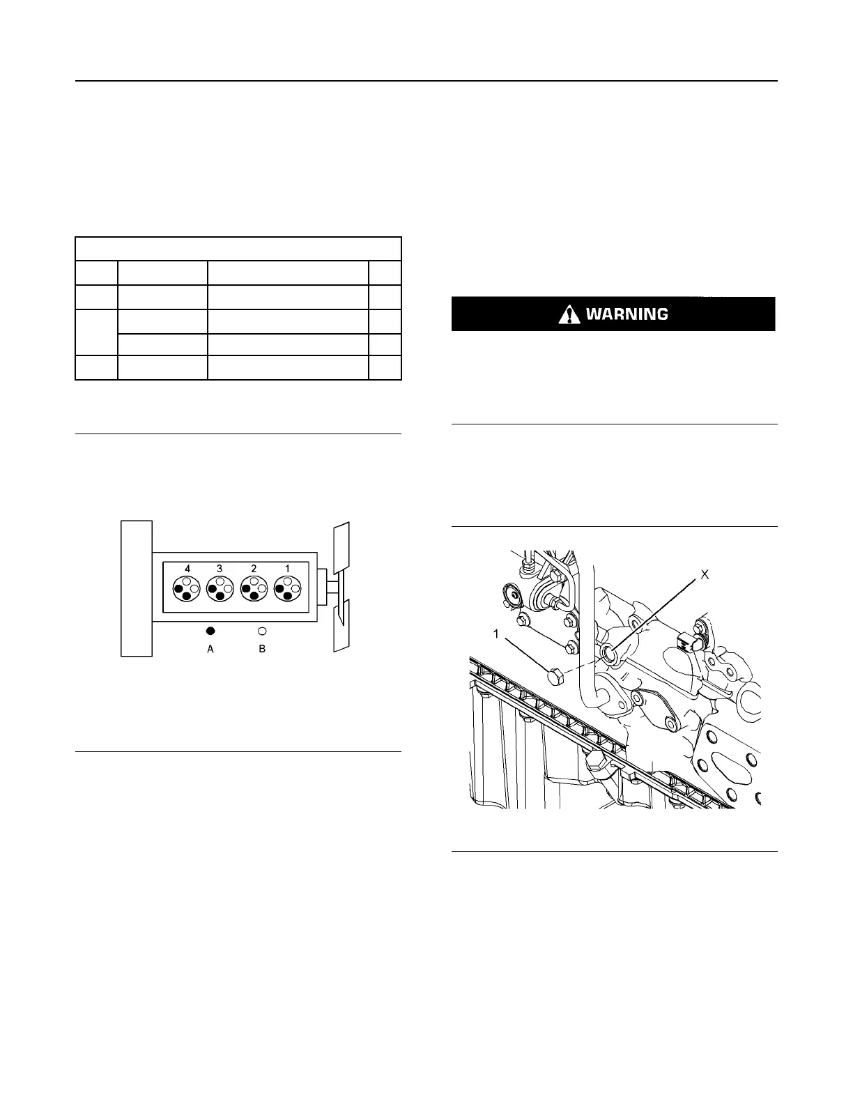
Illustration 84 g01335181
Cylinder and valve location
(A) Exhaust valve
(B) Inlet valve
Too much valve lash can cause some broken valve
stems, springs, and spring retainers. Damage to the
valve mechanism will produce emissions in excess of
the correct specification.
The hydraulic lifter will compensate for all normal
wear of the components of the valve train.
Too much valve lash can be an indication of the
following problems:
• Worn camshaft and valve lifters
• Worn rocker arms
• Bent pushrods
• Broken socket on the upper end of a pushrod
• Loose adjustment screw for the valve lash
• Issues with the hydraulic lifters
If the camshaft and valve lifters show rapid wear, look
for fuel in the lubrication oil or dirty lubrication oil as a
possible cause.
Valve Lash Check
Accidental engine starting can cause injury or
death to personnel.
To prevent accidental engine starting, turn the
ignition switch to the OFF position and place a do
not operate tag at the ignition switch location.
1. Remove the valve mechanism cover. Refer to
Disassembly and Assembly, “Valve Mechanism
Cover - Remove and Install” for the correct
procedure.
Illustration 85 g01958182
Typical example
2. Remove the plug (1) from the cylinder block. Use
Tooling (A) to rotate the crankshaft until the
number one piston is at the top center position.
Note: The number one piston may be on the
compression stroke or the exhaust stroke.
96 UENR4490-01
Air Inlet and Exhaust System
This document has been printed from SPI2. NOT FOR RESALE
 Loading...


