Starting Motor
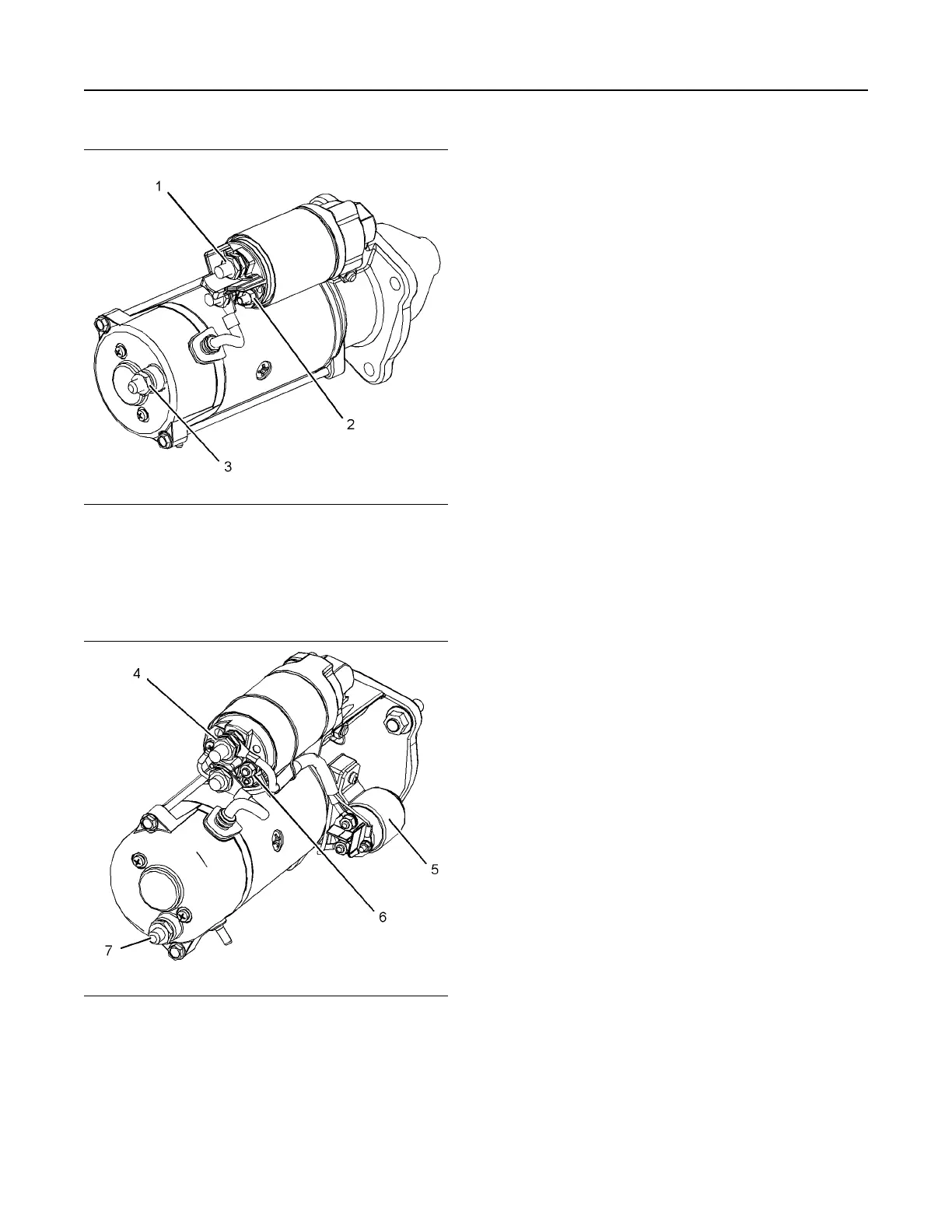
Illustration 31 g01964824
Typical example
12 V 4 kW Starting Motor
(1) Terminal 30 for connection of the battery cable
(2) Terminal 50 for connection of ignition switch
(3) Terminal 31 for connection of the ground
Illustration 32 g01964833
Typical example
24 V 5.5 kW Starting Motor
(4) Terminal 30 for connection of the battery cable
(5) Integrated Magnetic Switch (IMS)
(6) Terminal 50 for connection of ignition switch
(7) Terminal 31 for connection of the ground
The starting motor turns the engine via a gear on the
engine flywheel. The starting motor speed must be
high enough in order to initiate a sustained operation
of the fuel ignition in the cylinders.
The starting motor consists of the main armature and
a solenoid. The solenoid is a relay with two windings
Pull-In (PI) and Hold-In (HI). Upon activation of
ignition switch, both windings move the iron core by
electromagnets. The linkage from the iron core acts
to move the pinion toward the flywheel ring gear for
engagement. Upon complete engagement, the
solenoid completes the high current circuit that
supplies electric power to the main armature in order
to provide rotation. During cranking of the engine,
only the Hold-In (HI) winding is active.
The ignition switch is deactivated once the desired
engine speed has been achieved. The circuit is
disconnected. The armature will stop rotating. Return
springs that are located on the shafts and the
solenoid will disengage the pinion from flywheel ring
gear back to the rest position.
The armature of the starting motor and the
mechanical transmissions may be damaged if the
increases in the speed of the engine are greater than
the pinion of the starting motor. Damage may occur
when the engine is started or after the engine is
started. An overrunning clutch prevents damage to
the armature of the starting motor and mechanical
transmissions.
Certain higher powered starting motors are designed
with an Integrated Magnetic Switch (IMS). The
Integrated Magnetic Switch (IMS) is activated by the
ignition switch. The solenoid circuit then engages the
starting motor. The benefit of Integrated Magnetic
Switch (IMS) is a lower current in the ignition circuit
that will allow the engine ECM to control ignition
without the use of a relay.
Alternator
The electrical outputs of the alternator have the
following characteristics:
• Three-phase
• Full-wave
• Rectified
The alternator is an electro-mechanical component.
The alternator is driven by a belt from the crankshaft
pulley. The alternator charges the storage battery
during the engine operation.
The alternator is cooled by an external fan which is
mounted behind the pulley. The fan may be mounted
internally. The fan forces air through the holes in the
front of the alternator. The air exits through the holes
in the back of the alternator.
38 UENR4490-01
Engine Operation
This document has been printed from SPI2. NOT FOR RESALE





 To Next Page