.,,.-/
~·
-0
X
X
nT
0
x2
Position the wall plate template [05] at
your desired height. Level the wall
plate template and mark the pilot hole
locations.
Drill 6 pilot holes using a
3/8"(
1 0mm)
diameter drill bit. Make sure the depth
is
not less than 3"(75mm). Never drill
into the mortar between blocks.
~
~
Electric Drill
(Not Included)
3"(75mm)
[~!
09
Use
the hammer
to
knock anchors [A2]
into the wall.
Be
sure the anchors [A2]
are seated flush with the concrete or
brick surface.
~
Hammer
(NOT Included)
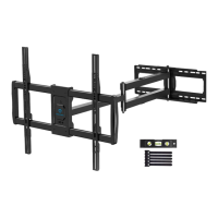
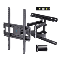
Install arm assembly / wall plate using
lag screws [A 1]. Tighten the lag screws
[A 1] only until they are pulled firmly
against the wall plate.
DO
NOT
over-tighten the lag screws [A 1].
HEAVY!
You
may
~
need assistance
with this step.
'
1/2"(13mm)
Socket Wrench
(Not included)
t
~
I
Option C (For
TV
with A
"Bump")
--------------------------,
i-:
C~
I
D2
/
D3
/
D4
1
[_
_____
........ _j
- , I ) I
I
''
' - -I
--,
:
':,
~
I 1 • 1
:;~~~~~~
®@
Option D
---
-
--~
~ :
' '
,l
ffll!l
ol
:
~
:
•
0
(if
needed)
----,
:
____
~--------------
___
:
For cable interference or inset holes,
use
spacers
[07]
to
create extra space
between the
TV
and
TV
brackets.
------L-- ----
''
''
''
'I
''
''
''
''
''
''
''
''
''
''
''
''
I ' - - - -
Alternate Spacer Setups
ae,=~~8~9
06
\
I
I.
m
E1
1
E2
1
E3
1
I
t
~~g!/
.
·t-
L: -
mlfil
:
I
- -
----"
®@