A
WARNING:
• Avoid potential personal injury
or
property damage! DO NOT
over-tighten
the lag screws
[A
1]. Tighten the lag screws
[A
1] only until they are pulled firmly
against the wall plate.
e
DO
NOT
USE
ANCHOR
[A2]
FOR
THIS STEP!
*
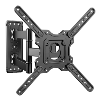
• Ensure the arm
assembly/
wall plate
[01]
is securely fastened
to
the wall before continuing
to
the next step.
• Any material covering the wall must
not
exceed
5/8"
(16mm).
• Nominal wood stud size: common 2 x
4"
(51
x 102mm) minimum
1 ½ x
3½"
(38 x 89mm).
• Stud center
must
be verified.
~
.
~
I
I
I
:~9rnrn
J :
; 16
•(
40~
.
.:::::.__
-ml---.
-,
·,
..,,
--l!
_____->~
~-
07
Use a stud finder (not included)
to
locate wood studs
or
use
an
awl
(not included) to verify the edges.
Mark the edge and center locations.
~88)
Stud
Finder
(Not
Included)
~
Awl
(Not
Included)
Position the wall plate template
[05]
at
your desired height and
line up the holes with your stud
center line. Level the wall plate
template
[05]
and mark the
holes.
)·
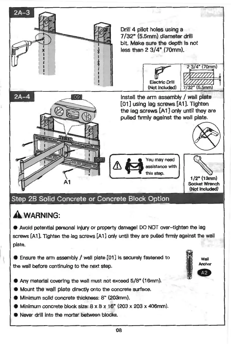
Drill 4 pilot holes using a
7
/32"
(5.5mm) diameter drill
bit. Make sure the depth is
not
less than 2
3/
4" (70mm).
Electric Drill
(Not Included)
2 374" {70mm)
~f
7
/32
" (5.5mm)
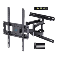
Install the arm assembly / wall plate
[01]
using lag screws
[A
1]. Tighten
the lag screws [A 1 ] only until they are
pulled firmly against the wall plate.
®
'
W
You may
need
& assistance with
th
is step.
A
WARNING:
•
Avoid
potential
personal
injury or property
damage!
DO
NOT
over-tighten
the
lag
screws
[A
1
].
Tighten the
lag
screws
[A
1]
only
until
they
are
pulled
firmly
against
the
wall
plate.
•
Ensure
the
arm
assembly
/
wall
plate
(01] is
securely
fastened to
the
wall
before continuing to
the
next
step.
•
Any
material covering
the
wall
must
not
exceed
5/8
"
(16mm).
•
Mount
the wall plate directly
onto
the concrete surface.
•
Minimum
solid
concrete thickness: 8"
(203mm)
.
•
Minimum
concrete block
size
: 8 x 8 x 16"
(203
x
203
x
406mm)
.
•
Never
drill into
the
mortar
between
blocks.
08
Wall
Anchor
fD