TB 100
PAG. 20 Cod. 29050055 Rev.01 Edit: 09/2015
Replacement
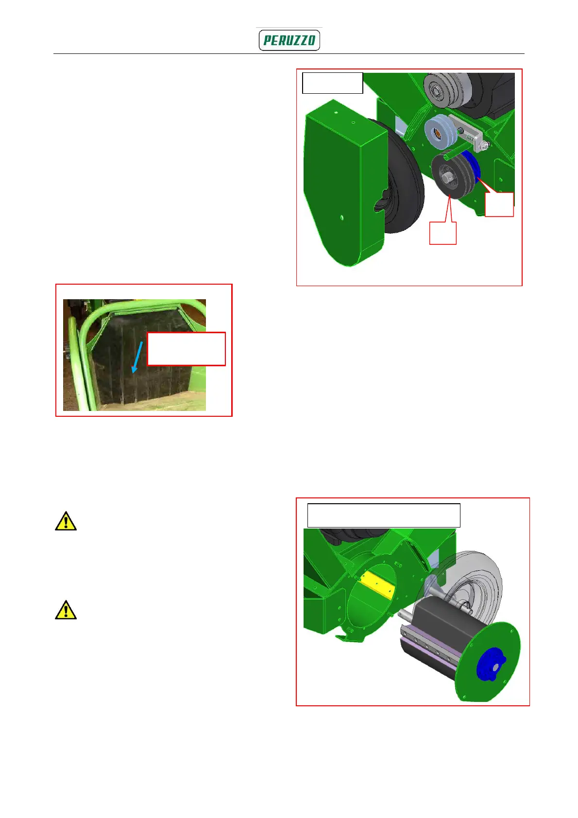
6.5.5a Release the pulley bolt and slacken
the tensioning screw to allow the
drive belts to be removed (see
section 6.5.3. - 6.5.4)
6.5.6 Fit the brand-new belts, ensuring
they lie snugly in the pulley grooves.
6.5.7 Tension the belts, tighten the pulley.
bolts and replace the guard securely.
Note: Re-tension the brand-new belts
after 5 working hours (engine driven
version only).
6.6 Infeed chute flaps (Fig. 6.6)
Two slitted flaps protect the operator from
material being thrown back up the infeed
chute.
6.6.1 Replace the flaps, if damaged.
CAUTION! Do not operate with any
missing or damaged flaps.
6.7 Cutter blade servicing
CAUTION! Always press the STOP
button, switch the engine to position 0 and
check for any rotation before carrying out
any maintenance. In the tractor driven
version, or the one with the hydraulic
engine, pull the hand brake, and take the
ignition key out. Check for any rotation
before commencing any maintenance.
The cutter cassette is removed as a unit to
service the cutter blades.
6.7.1 Remove the drive belt guards.
6.7.2 Remove the drive belts, as referred
to in section 6.5 above
6.7.3 Loosen up the clamp and remove the
lower drive wheel (A). Remove the
pin (B) blocking the cutter unit in
place - Fig. 6.7.
6.7.4 Unscrew the nuts (C) and carefully
remove the cutter unit, as shown on
Fig. 6.7.1
Fig. 6.6 Infeed chute rubber flaps
Rubber Flaps
A
B
Fig. 6.7
Fig. 6.7.1