BR 230/400-10...400 11
11. Commissioning
The device is to be put into operation in 3 steps::
1. Mounting
2. Connection and
3. Parameter setting
11.1 Mounting instructions
Caution: Danger to life through electric shock!
The following conditions are to be complied with in order to ensure a safe
and reliable operation of the BR ...:
1. The device series BR ... is to be used under overvoltage conditions of the
category III.
2. Make sure that pollution degree 2 or better, in accordance with IEC664, is
complied with.
3. The device is to be installed into a housing (min. degree of protection: IP54).
4. The device must be operated without being exposed to contamination by
water, oil, carbon deposits, dust, etc..
Warning:
Make sure that a minimum distance to adjoining devices is kept. Above and
underneath the housing a minimum distance of 50mm is to be kept.
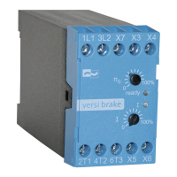
11.2 Connection
The braking device has to be connected according to the attached connection diagram. For other
connections refer to the factory.
Note: Further connection proposals for special circuit arrangements are available
via our hompage at www.peter-electronic.com.
Note: Prior to putting the motor brake into operation, the wiring has to be checked.
To ensure a reliable operation it is important to keep to the interlocking conditions:
1. In order to initiate braking, a potential-free break-contact of the main contactor is
necessary, i.e., when the motor contactor is dropped out the terminals X3,X4 of the braking
device are connected.
2. The interlocking contact of the braking unit (terminal X5,X6) has to be looped into the
control circuit of the motor contactor, so that the motor contactor cannot pull in during
braking.