18 BR 230/400-10...400
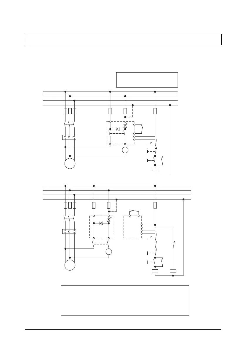
14. Typical connections
14.1 Connection diagramm
moving-iron
instrument
The limit values for emitted interference according to the applicable device standards do not rule out
the possibility that receivers and susceptible electronic devices within a radius of 10m are subjected
to interference.
If such interference, that is definitely attributable to the operation of the braking devices "BR",
occurs, the emitted interference can be reduced by taking appropriate measures.
Such measures are, e.g.:
to connect reactors (3mH) or a suitable mains filter in series before the soft starter, or to connect
X-capacitors (0,15µ F) in parallel to the supply voltage terminals.
F1 F2
Attention:
If, in spite of a long braking time, the braking
current is instantly switched off,
the braking current is adjusted to a too high value.
3
~
EMC
W
M
V
U
F4
K1
UV
A
power
terminals
L2/NL1
BR 230-40 ... 400
BR 400-40 ... 400
N
L1
L3
L2
BR 230-10 ... 20
BR 400-10 ... 20
L1
N
L3
L2
WU
V
M
3
~
F1
F4
K1
F2
F3
braking
contactor
A2
motor
contactor
K1
A1
K2
OFF
K2
X5
control
unit
X6
X2
X3
X1
X4
K1
K1ON
K2 K1
F4
A2
A1
F4
OFF
A
moving-iron
instrument
motor contactor
K1
K1
A1
A2
ON
Typ BR 230
K1
UV
L2/NL1
X3
X4
X5
X6
F3
Typ BR 230