Do you have a question about the PEUGEOT XS1P37QMA-2 and is the answer not in the manual?
Indicates that the product or package can be recycled.
Product can irritate skin, eyes, and respiratory organs. Avoid contact and wear protective gear.
Product is flammable. Keep away from heat sources and flames.
Product can damage living tissues or surfaces. Avoid contact and wear protective gear.
Product can explode under certain circumstances. Avoid impacts, friction, sparks, and heat.
Product affects fauna and flora. Do not dump in dustbins or sinks.
Product can affect health if inhaled, ingested, or in contact with skin. Seek medical advice if unwell.
Component is toxic and hazardous to environment. Bring back to merchant or collection point.
Operation can be dangerous for people. Follow recommendations for safety.
Operation that can be dangerous for people. Recommendations must be respected.
Operation is hazardous to the vehicle. Follow specific procedures to avoid damage.
Operation must be carried out in strict compliance with documents. Non-compliance can cause damage.
Operation that can be difficult. Provides key information to make procedures easier.
Indicates parts to be lubricated during assembly to avoid damage.
Indicates parts to be greased during assembly to avoid damage.
Indicates parts to be glued during assembly to avoid damage.
Indicates that a new part should be used for assembly to avoid damage.
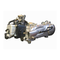
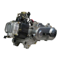
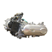
Identifies the engine model or series.
Describes the engine configuration, e.g., 4-stroke single-cylinder.
Details the engine cooling method, e.g., forced air.
Specifies the cylinder bore and piston stroke dimensions.
States the engine's displacement in cubic centimeters.
Indicates the maximum engine power and RPM.
Shows the maximum torque and the RPM at which it occurs.
Describes the engine lubrication system and method.
Details the transmission type, e.g., pulleys and belt.
Specifies the type of clutch used, e.g., centrifugal automatic.
Indicates the exhaust system type, e.g., catalytic.
Specifies the recommended spark plug model.
Details the magneto flywheel specifications.
Identifies the fuel delivery system and carburetor model.
Lists the emission or operational standards the engine complies with.
Specifies the oil capacities for various engine components.
Specifies the oil capacity for the crankcase.
Specifies the oil capacity for the relay box.
Engine designed for unleaded fuel only; never use petrol/oil mixture.
Fuel pipes must be changed if worn; use specific clips.
Petrol is highly flammable; avoid smoking and flames in the working area.
Specifies the tightening torque for the spark plug.
Specifies the tightening torque for the filler cap.
Specifies the tightening torque for the screen.
Specifies tightening torques for cylinder head nuts and screws.
Specifies the tightening torque for the camshaft gear cover.
Specifies the tightening torque for the camshaft gear.
Specifies the tightening torque for valve clearance covers.
Specifies the tightening torque for the automatic tensioner.
Specifies the tightening torque for the automatic tensioner plug.
Specifies the tightening torque for the chain tensioner.
Specifies the tightening torque for the inlet manifold.
Specifies the tightening torque for the cylinder casings.
Specifies the tightening torque for the RH casing cover.
Specifies the tightening torque for the freewheel.
Specifies the tightening torque for the oil pump.
Specifies the tightening torque for the transmission cover.
Specifies the tightening torque for the relay box cover.
Specifies the tightening torque for the relay box drain plug.
Specifies the tightening torque for the starter motor.
Specifies the tightening torque for the rotor.
Specifies the tightening torque for the turbine.
Specifies the tightening torque for the stator.
Specifies the tightening torque for the engine speed sensor.
Specifies the tightening torque for the drive pulley.
Specifies the tightening torque for the driven pulley.
Specifies the tightening torque for the clutch plate and shoes.
Tool for mounting the engine during service.
Tool used for manipulating engine valves.
Protective component for specific tools or parts.
Tool for removing bearings from shafts or housings.
Tool designed to remove the flywheel.
Adapter for engine mounting systems.
Tool used to compress clutch components.
Tool for installing or handling piston seals.
Wrench with adjustable pins for specific fasteners.
Pipe wrench of a specific size for certain nuts or fittings.
Specialized tool for the freewheel nut.
Tool used for heating components, often for removal or fitting.
Torque wrench for precise tightening within a specific range.
Tool for extracting bearings using inertia.
Torque wrench for precise tightening within a specific range.
Torque wrench for precise tightening within a specific range.
Procedures for safely mounting the engine for maintenance.
Steps for draining and refilling the engine oil, including torque specs.
Steps to remove the primary transmission cover, including torque.
Steps to remove the drive pulley, including tool usage and torque.
Steps to remove the driven pulley, including tool usage and torque.
Instructions for replacing bearings in the drive pulley.
Procedure for measuring belt width and checking for damage.
General reassembly instructions for primary transmission components.
Steps to remove the clutch lining assembly, including measurement and tool use.
Steps for refitting the clutch lining assembly, including lubrication and torques.
Steps to remove the kick starter system components.
Steps for fitting the kick starter system components.
Steps to remove the secondary transmission cover and components, including torques.
Procedure for replacing bearings in the crankcase and relay box cover.
Steps to remove the main carburettor unit.
Steps to remove the choke assembly from the carburettor.
Steps to remove the starter holder and its associated gasket.
Steps to remove the throttle valve assembly from the carburettor.
Steps to remove the float chamber, needle valve, and jets.
Steps to remove float, pin, needle valve, idle jet, main jet, and needle well.
Checking the condition of the needle valve, seat, and float chamber O-ring.
Steps to remove the mixture control screw and note its position.
Steps to remove the pick-up pump components, including bushing and piston.
Steps to remove the jet, spring, and ball from the suction valve.
Steps to remove the enrichment device cover, spring, membrane, and O-ring.
Steps to remove the carburetor warming resistor and earthing connection.
Steps to remove the inlet coupling and plastic spacer, checking the O-ring.
Steps to remove the flywheel, including volute, housing, and turbine.
Steps to remove the flywheel nut using a specific tool and torque.
Using specific tools to remove the flywheel rotor.
Steps to remove the stator and sensor assembly.
Steps to remove the overrunning clutch after flywheel removal.
Removing gasket, pins, starter ring, and starter dog.
Using tools to remove the overrunning clutch nut.
Procedure to check the rotational direction and blockage of the overrunning clutch.
Using a tool to fit a new gasket to the magneto housing.
Steps to remove the cylinder head, including housing, cover, and timing marks.
Removing the chain tensioner plug, seal, and spring.
Slackening the chain tensioner and removing the camshaft gear.
Steps to remove the cylinder head securing nuts and bolts.
Removing the cylinder head, metal gasket, and centring pillars.
Steps to remove the camshaft, rockers, stopper plate, and adjustment covers.
Removing pins from rockers using a screw.
Steps to remove valves and stem seals using a valve lifter.
Guidance on replacing valve stem seals and lubricating components.
Recommends lubricating camshaft bearings, rocker shafts, and valve stems.
Steps to remove the cylinder head, chain guide, cylinder, base gasket, and piston.
Removing circlips, gudgeon pin, and the piston.
Procedure to check cylinder for scoring, seizure, and measure diameter.
Procedure to check piston for scoring, seizure, and measure diameter.
Steps to measure piston ring gap using a feeler gauge.
Order and method for installing oil control and compression rings.
Installing the piston with correct orientation and fitting circlips.
Positioning piston ring gaps and fitting the cylinder.
Installing cylinder base gasket and guiding pillars.
Fitting cylinder over piston by compressing rings.
Installing chain and chain guide tensioner.
Steps to install cylinder head, including tightening nuts and bolts.
Rotating flywheel and fitting camshaft gear to align timing marks.
Tightening the camshaft gear screw.
Installing the chain tensioner gasket, tensioner, and screws.
Verifying timing marks alignment after installation.
Installing the timing gear cover.
Adjusting valve clearance using feeler gauges and follower screw.
Procedure to check valve clearances using feeler gauges.
Steps to remove primary drive, overrunning clutch, cylinder, piston, and starter motor.
Removing drive gear, circlip, and oil pump gear from the crankcase.
Removing RH casing, screws, pillars, and paper gasket.
Disengaging the timing chain from the crankshaft gear.
Removing the crankshaft and conrod assembly.
Checking big end side play and crankshaft runout.
Installing the conrod and crankshaft assembly with gasket and timing chain.
Trimming the casing gasket after assembly.