4. Toke out screw E (Photo
28)
at
the back
of
he
machine,
the
take-up
crank, whicli
5. Turn
the
balance
wheel
until
the
set
screw
for*
is positioned in the needle bar crank, can be reached through hole G.
(Photo 28).
6. Loosen the
take-up
crank
set
screw.
7.
Loosen
the set screw for the take-up
link
stijd.
8. Unscrew the
top
cover ond pull the packing
stud
of the
take-up
link.
out
of
the
hollow
hinge
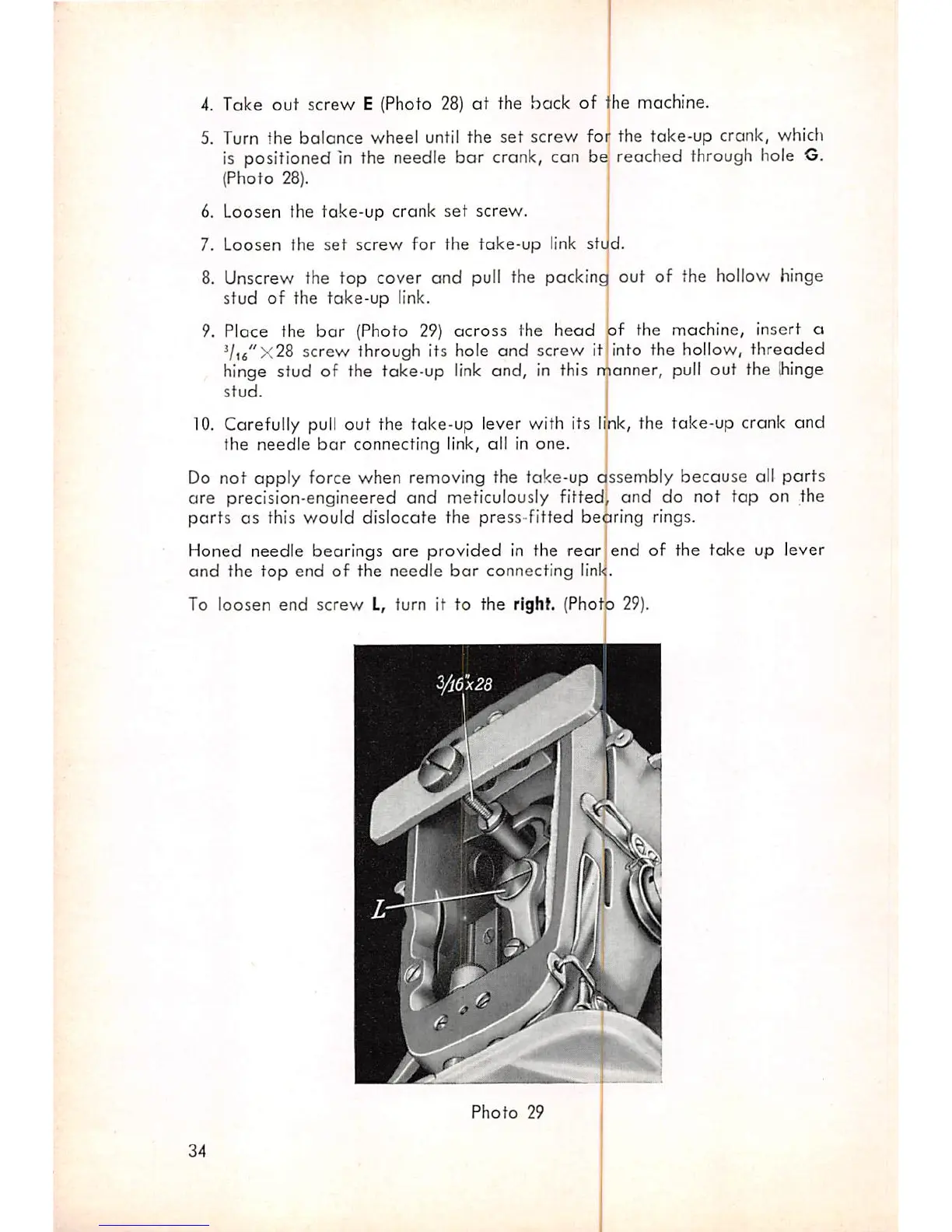
9. Ploce the
bar
(Photo 29)
across
the
head
Vifi"x28
screw
through its hole
ond
screw
it
hinge stud of the take-up
link
and, in this manner,
pull
out the
ihinge
stud.
sf
the
machine,
insert
o
into
the
hollow,
threaded
10.
Carefully
pull
out
the
take-up
lever
with
its
ijik,
the
take-up
crank
and
the
needle
bar
connecting link, all in
one.
ssembly
because
all
parts
and
do
not
tap
on the
Do
not
apply
force when removing the take-up c
are
precision-engineered
and
meticulously fitted
parts as this would dislocate the press-fitted bedring rings.
Honed needle bearings
are
provided in the
rear
and
the
top
end of the needle
bar
connecting
linl<
To
loosen
end
screw
L, turn it to the right. (Phot
Photo
29
34
end
of
the
take
up
lever
0 29).