6
Adjustment
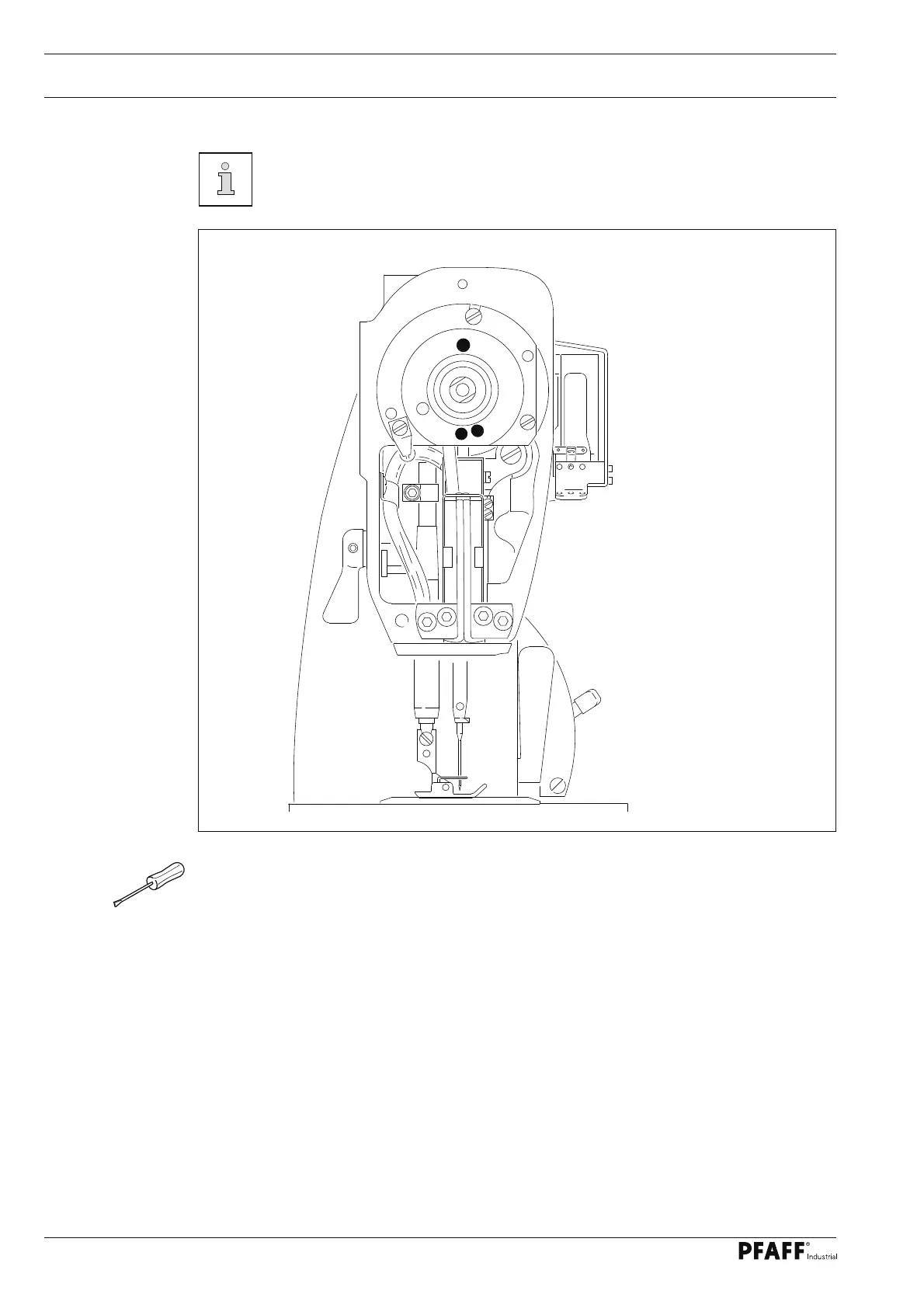
Fig. 1 - 01
1.04 Control and adjustment aids
By adjusting the holes 1, 3 and 4 with the adjustment pin ( ∅ 5 mm) the
required needle bar positions can be set exactly.
● Turn the balance wheel until the needle by is approximately in the required postion.
● Insert the adjustment pin into the appropriate adjustment hole and apply pressure.
● Turn the balance wheel slightly backwards and forwards, until the adjustment pin slips
into the rear crank recess, blocking the machine.
Adjustment hole 1 = top dead center of the needle bar (TDC)
Adjustment hole 3 = bottom dead center of the needle bar (BDC)
Adjustment hole 4 = 0.8 mm before the top dead center of the needle bar (0.8 before TDC)
1
3
4
 Loading...