General Information:
Installation:
When tightening the bolts the gasket should be evenly compressed half the
thickness of the gasket.
Over compression of the gasket will not provide a better seal to the enclosure.
MAKE SURE NOTHING IS MOUNTED 6 INCHES IN FRONT OF INLET FAN.
CAUTION!
If the cooling unit is mounted on a switch cabinet door, it must be confirmed that the
hinge can support the additional weight or that the switch cabinet will not topple over
when the door is opened.
CAUTION!
Make cutouts required to the enclosure prior to mounting the air conditioner. Make
sure that metal particles are not allowed to enter the enclosure.
Electrical Connection:
All power connections and repairs should be carried out by an authorized
trained electrician.
No other equipment should be connected to this circuit to prevent overloading.
Both main voltage and frequency must correspond to the nominal values indi-
cated on the nameplate of the cooling units.
ATTENTION!
THE COOLING UNIT MAY BE DAMAGED IF THE VOLTAGE IS TOO HIGH.
Testing and Startup Procedure:
Operating Conditions:
Door Contact: (All Units)
To avoid an increased production of condensate and for safety reasons a
door limit switch should be connected to the terminals provided
(see circuit diagram, housing cover or supplement.)
Centralized Fault Indication:
The signal of a fault in the cooling unit is caused by the high pressure
switch being opened.
This fault is displayed by the breaking of a potential-free contact.
Therefore, if the fault wire breaks, a fault signal will be simulated.
WARNING!
THE CONTACTS MAY BE LOADED WITH MAX. 230V, 10A.
Minimum Circuit Protection Class CC
NAME PLATE
125% of Run Load Amps
Short Circuit Protection for:
115/230V: 1000 Amps; 400/460V: 5000 Amps
Hz
+ / - 3Hz + / - 10%
Handling:
Storage:
Failure to observe these instructions will render the warranty provisions null and void.
If it is necessary to store the air conditioner in a horizontal position prior to mounting,
make sure that it is placed in a vertical position for a minimum of 1 hour prior to
starting the unit.
Running the compressor without oil in the compressor will cause permanent damage
to the air conditioner, and void the warranty of the unit.
TEST THE UNIT FOR FUNCTIONALITY PRIOR TO MOUNTING THE
AIR CONDITIONER ON THE ENCLOSURE.
Terminal Connections:
Ground
Neutral
Power
Permanent Connection Detail
[Drilling Template Available on http://www.pfannenbergusa.com]
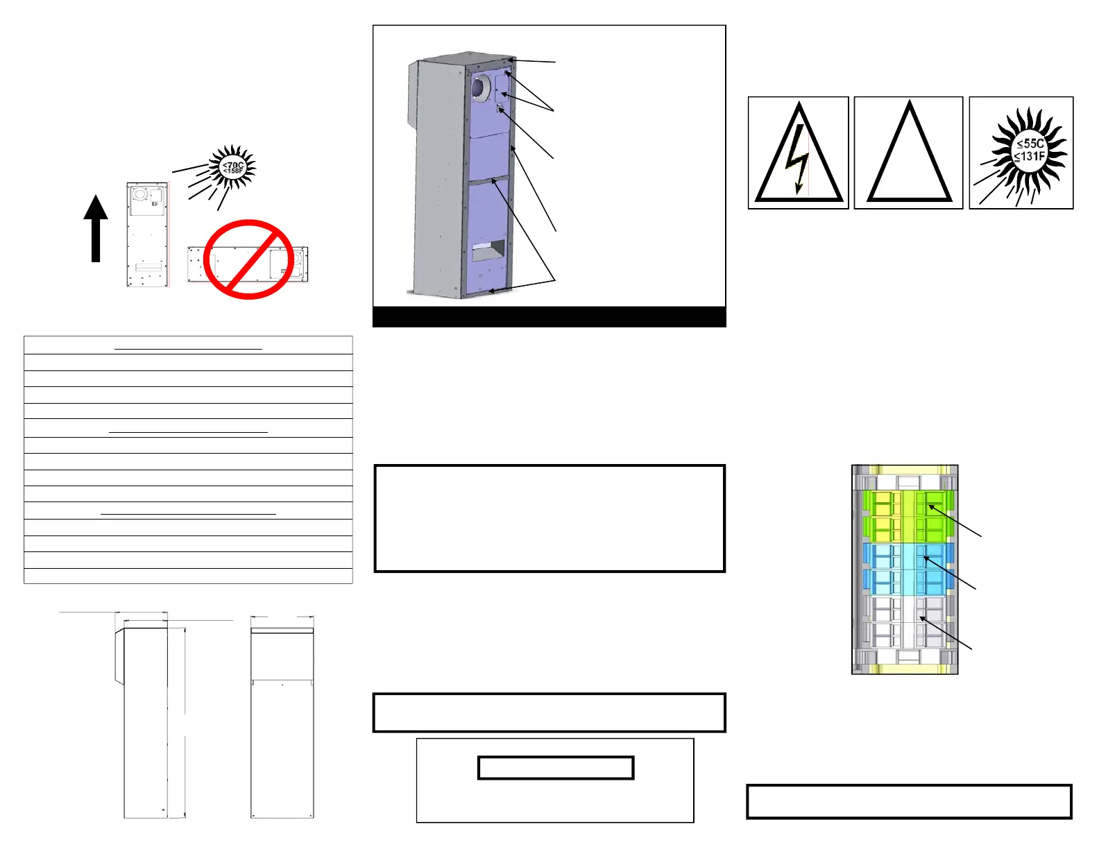
Mounting Insulation Installation:
Side Iso—Side Iso must be applied
on mounting holes on left and right
sides.
Top Iso—Ensure notch and groove
match sides.
Must extend to side Iso; mid and
bottom of unit.
Door Contact
Electrical Connection
When unit is plugged in, the drawn-in switch cabinet internal air tempera-
ture is measured by a temperature sensor.
If the compressor and condenser fan do not turn on, adjust the thermostat
down to a lower setting that will call for the compressor and condenser
fan.
You should feel a temperature difference between the inlet and outlet air.
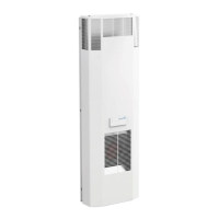
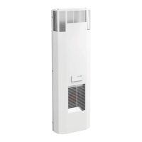
325mm
[12 13/16”]
WITH RAIN HOOD
DTS 3261 & DTS 3281
269mm
[10 5/8”]
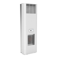
WITHOUT RAIN HOOD
DTS 3241
395mm
[15 9/16”]
1208mm
[47 9/16”]
Technical Information: 115 Volt 60 Hz
Amp Draw: 15.9 Amps
Capacity (95F/95F)[35C/35C]: 3241/61/81: 6825 BTUH [2000 W]
Capacity (122F/95F)[50C/35C]: 3241/61/81: 6313 BTUH [1850 W]
3241:54kg [119lbs]; 3261:56kg [123.5lbs]; 3281:60kg [132.2lbs] Weight:
Technical Information: 230 Volt 50/60 Hz
Amp Draw: 6.2 Amps
Capacity (95F/95F)[35C/35C]: 3241/61/81: 6825 BTUH [2000 W]
Capacity (122F/95F)[50C/35C]: 3241/61/81: 6313 BTUH [1850 W]
3241:54kg [119lbs]; 3261:56kg [123.5lbs]; 3281:60kg [132.2lbs] Weight:
Technical Information: 400/460 Volt 50/60 Hz
Amp Draw: 3.5 / 3.0 Amps
Capacity (95F/95F)[35C/35C]: 3241/61/81: 6825 BTUH [2000 W]
Capacity (122F/95F)[50C/35C]: 3241/61/81: 6313 BTUH [1850 W]
3241:61kg [135lbs]; 3261:63kg [139lbs]; 3281:67kg [147lbs] Weight:
 Loading...