GB 02866 - Edition 03 - April 12
3/4
A 20
Description
Internal equipment of
the pumps
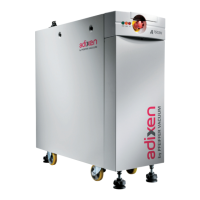
The A3-P Range pumping systems are designed for medium processes,
so they are equipped with:
Nitrogen injection and water cooling circuit optimized to avoid
deposition and condensation,
Temperature regulation device.
A103P cooling circuit
(principle schematic)
7ATERINLET
)3 43 4343 43 %3
-OTOR
-ONITORING
%LECTRICALBOX
!NTISUCKBACKVALVE
7ATEROUTLET
%XHAUST
)NLET
&UNCTIONALBLOCK
1 : Water flow switch (warning)
2 : Water solenoid valve
3 : Pump temperature sensor (warning and hazard)
4 : Motor temperature switch (warning and hazard)
IS : Inlet stage
TS : Transfer stage
ES : Exhaust stage
A603P/A1003P cooling
circuit
(principle schematic)
7ATERINLET
)NLET
)3 43 4343 43 %3
-ONITORING
%LECTRICALBOX
!NTISUCKBACKVALVE
7ATEROUTLET
%XHAUST
&UNCTIONALBLOCK
2OOTS
-OTOR
1 : Water flow switch (warning)
2 : Water solenoid valve
3 : Pump temperature sensor (warning and hazard)
4 : Motor temperature switch (warning and hazard)
5 : Roots temperature switch (warning and hazard)
IS : Inlet stage
TS : Transfer stage
ES : Exhaust stage
adixen Vacuum Products - Operating instructions - A3P Series
 Loading...