Do you have a question about the Pfeiffer TC400 and is the answer not in the manual?
Describes the functioning of the designated product and provides information for safe use.
Explains safety instructions, pictograph definitions, and abbreviations used in the manual.
Covers safe electrical installation, danger of electric shock, and power supply requirements.
Details CE conformity and the invalidity of declarations if the product is modified.
Identifies the TC 400 as an integrated component for driving, monitoring, and controlling turbopumps.
Specifies ambient conditions for installation and operation of TC 400 drive units.
Describes the core functions and operational capabilities of the electronic drive unit.
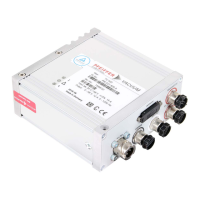
Describes the purpose and connections of DC in, accessory, PV.can, remote, and RS485 ports.
Details the pinout and function for the 26-pole D-Sub connector for remote control.
Explains the use of digital inputs, outputs, and relay contacts for remote control functions.
Describes connecting Pfeiffer Vacuum display units (DCU/HPU) or a PC via the RS485 interface.
Provides instructions and diagrams for connecting external operating units or a PC via RS485.
Explains that all function-relevant variables are stored as parameters with numbers and designations.
Provides a detailed overview of control commands and their functions, data types, and access methods.
Details accessory connection and remote interface configuration options.
Covers operational modes, gas type settings, speed control, and safety monitoring.
Defines the structure and ASCII character set of telegrams exchanged with the electronic drive unit.
Provides examples and formats for data requests, control commands, and error messages.
Lists and describes the data types used in the RS485 protocol communication.
Explains that malfunctions result in warnings or error messages displayed via LEDs and error codes.
Describes how LEDs on the drive unit indicate basic operating conditions and malfunctions.
Lists potential problems, causes, and remedies for various error codes.
| Model | TC400 |
|---|---|
| Category | Controller |
| Protection Class | IP20 |
| Display | LCD |
| Operating Temperature | 0 to 50 °C |
| Control Type | PID |
| Power Supply | 100 - 240 VAC |
| Compatible Pumps | Pfeiffer Vacuum Pumps |
| Communication Interface | RS485 |
| Output Type | Relay, Analog |