8
Connection "remote"
5 Connection "remote"
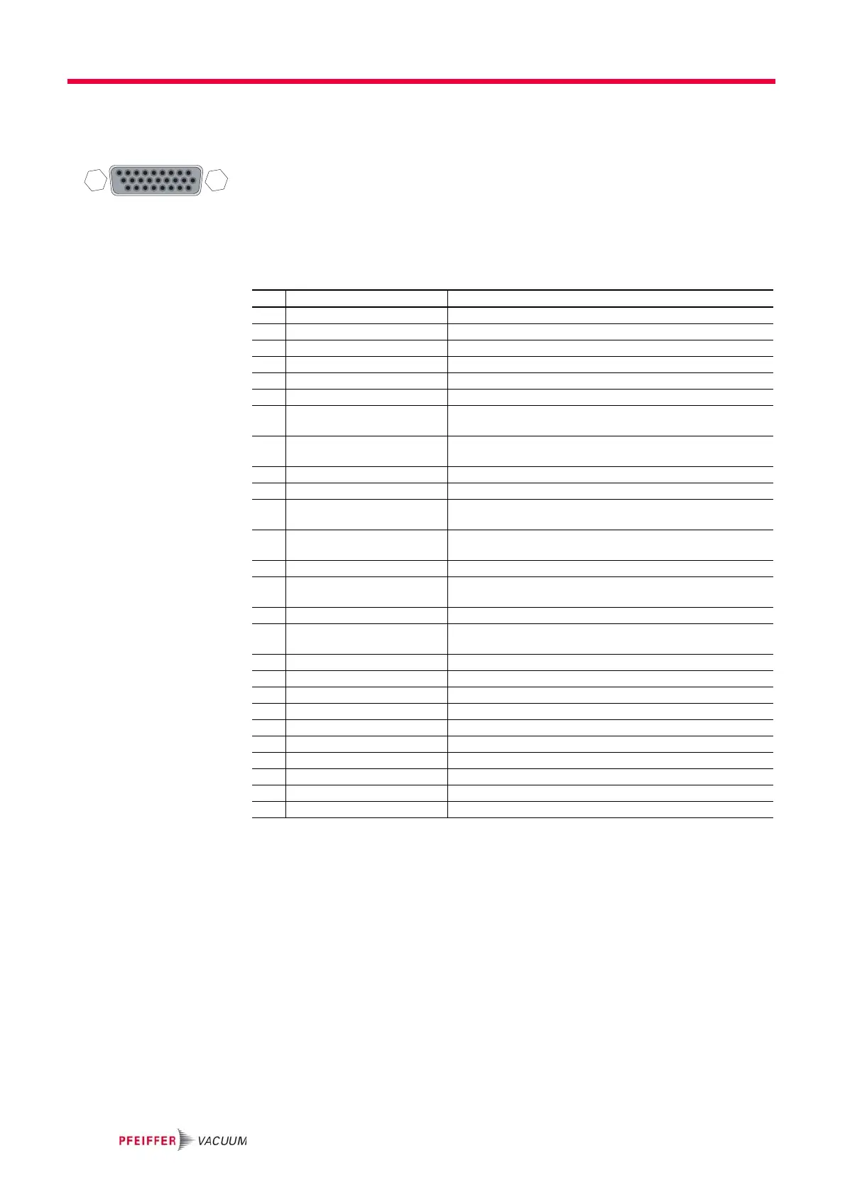
Remote control options are provided via the 26-pole D-Sub connector with the des-
ignation ”remote“ on the electronic drive unit.
Remove the remote plug from the TC 400 and connect a remote control unit. Pin
assignment of the connector according to table.
Shielded connectors and cables must be used.
5.1 Pin assignment
5.2 Operation via "remote" connection
+24 VDC* Output /
Pin 1
Inputs 2 - 6 and the connections to Pins 10, 13, 14 are activated by connecting them
with +24 VDC to Pin 1 (active high). They can also be activated via an external PLC.
The functions are deactivated by "PLC high level" and by "PLC low level".
• PLC high level: +13 V to +33 V
• PLC low level: -33 V to +7 V
• Ri: 7 kΩ
Inputs The digital inputs at connection "remote" are used to connect various functions of
the electronic drive unit. Functions are assigned to the inputs DI1 - DI2 ex factory.
These can be configured via interface RS485 and the Pfeiffer Vacuum parameter
set.
19
1018
1926
Pin Function Designation factory settings
1 +24 VDC output (V+) Reference voltage for all digital in- and outputs
2 DI1 Enable venting; open: no; V+: yes
3 DI Motor pump Drive motor; open: off; V+: on
4 DI Pumping station Open: off; V+: on and error acknowledgement
5 DI Standby Standby rotation speed; open: off; V+: on
6 DI2 Heating; open: off; V+: on
7 AI+ Rotation speed setting
mode
Set value in rotation speed setting mode;
2-10 VDC = 20-100% of the nominal rotation speed
8 DO1 Rotation speed switch point attained; GND:no;
V+: yes (I
max
=50mA/24 V)
9 DO2 GND: error; V+: no error (I
max
= 50 mA/24 V)
10 DI3 Sealing gas; open: off; V+: on
11 AI- Rotation speed setting
mode GND
Set value in rotation speed setting mode; GND
12 AO1 Actual rotation speed; 0-10 VDC is equivalent to 0-100%;
R
L
> 10 kΩ
13 DI Error acknowledgement Error acknowledgement: V+ pulse (min 500 ms)
14 DI Remote priority Control via interface "remote"; open: off
V+: set and priority over other digital inputs
15 Relais 1 Connection to Pin 16 if relay 1 is inactive
16 Relais 1 Rotation speed switchpoint attained;
relay contact 1 (U
max
= 50 VDC; I
max
= 1 A)
17 Relais 1 Connection to Pin 16 if relay 1 is active
18 Relais 2 Connection to Pin 19 if relay 2 is inactive
19 Relais 2 No error; relay contact 2 (U
max
= 50 VDC; I
max
= 1 A)
20 Relais 2 Connection to Pin 19 if relay 2 is active
21 Relais 3 Connection to Pin 22 if relay 3 is inactive
22 Relais 3 Warning; relay contact 3 (U
max
= 50 VDC; I
max
= 1 A)
23 DO Remote priority GND: off; V+: remote priority active
24 RS485 D+ according to specifications and Pfeiffer Vacuum protocol
25 RS485 D- according to specifications and Pfeiffer Vacuum protocol
26 Ground (GND) Reference ground for all digital inputs and all outputs
 Loading...