6
Product description
3.3 Function
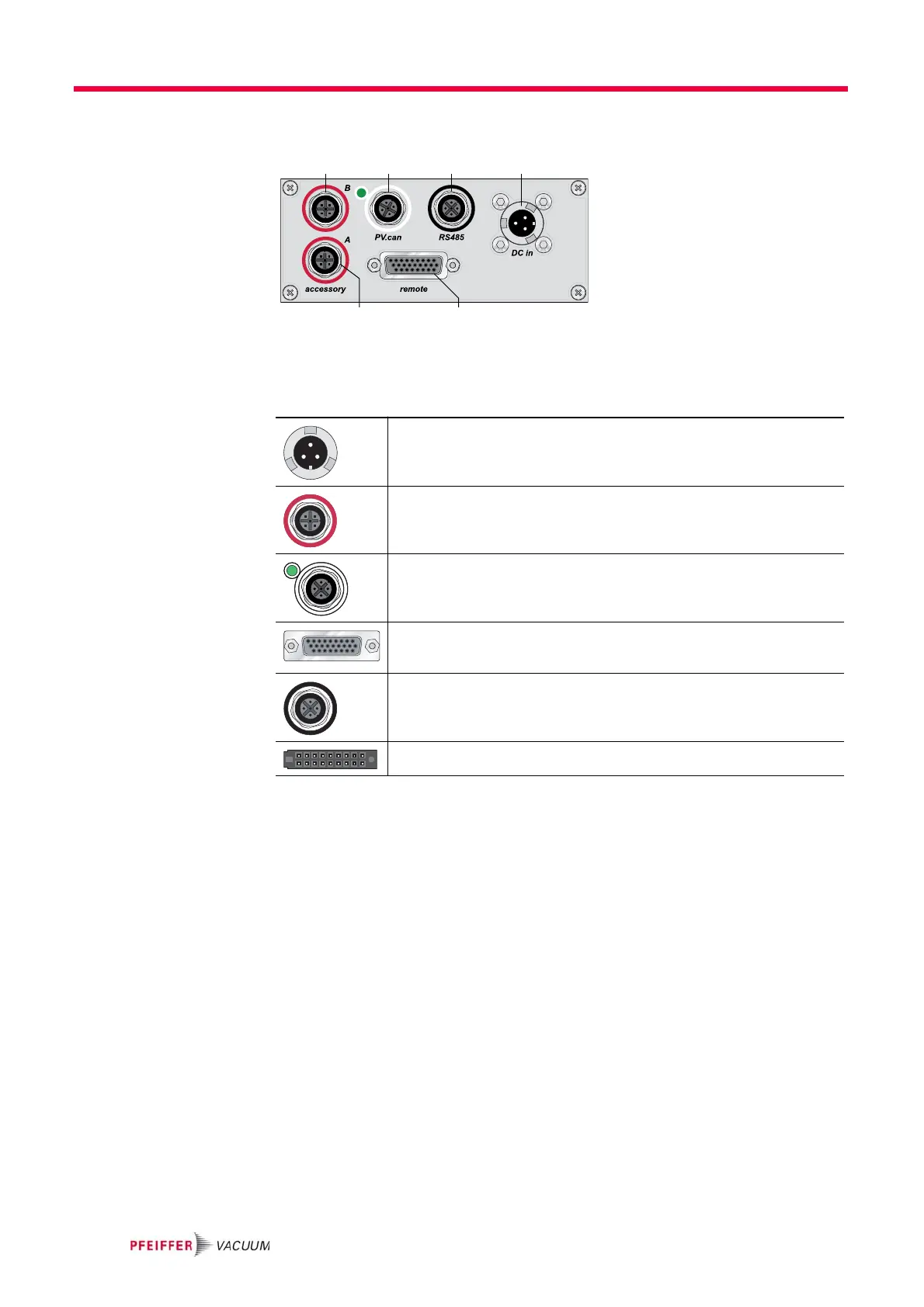
Fig. 1: Standard panel of the TC 400
3.4 General connection description
8a Connection "DC in"
8b Connection "accessory A+B"
8c Connection "remote"
8d Service connection "PV.can"
8e Connection "RS485"
8b
8d
8b
8c
8e 8a
DC in
1
Casing plug with bayonet locking for the voltage supply between Pfeiffer Vac-
uum mains packs and the electronic drive unit TC.
1. "DC in" and "accessory" are already described in the operating instructions of the
turbopump.
accessory
M12 socket with screw coupling for the connection of Pfeiffer Vacuum acces-
sories. The use of a Y-connector enables double assignment of one connec-
tion.
PV.can
M12 casing socket with screw coupling and LED. The connection "PV.can"
serves to service purposes exclusively.
remote
High Density D-sub 26 pole female socket for the connection of a remote con-
trol.
RS485
M12 socket with screw coupling for the connection of a Pfeiffer Vacuum con-
trol unit or a PC. The use of a Y-connector enables the series connection in a
bus system.
Casing socket on the rear side of the electronic drive unit for the connection
to the turbopump.