21
The Pfeiffer Vacuum parameter set
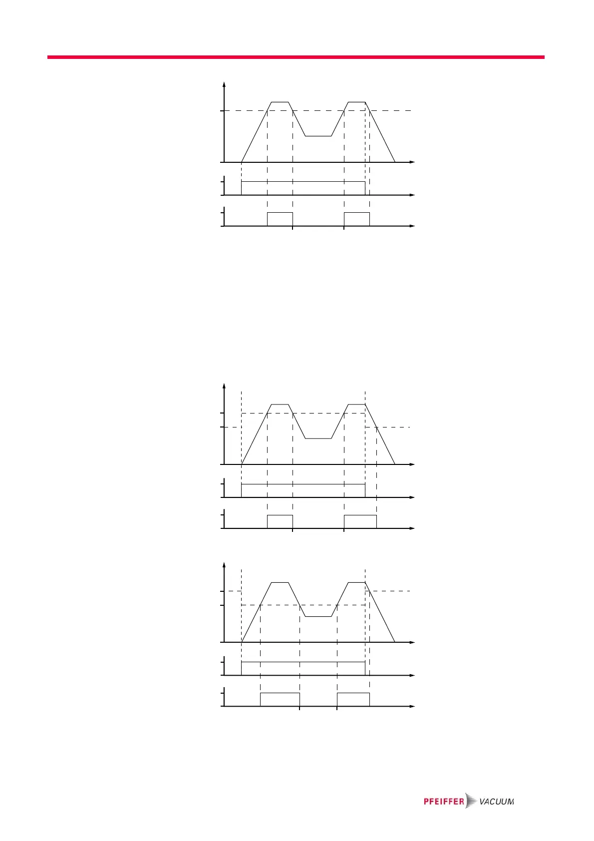
Fig. 5: Example for the configuration rotation speed switch point 1 active
Rotation speed switchpoint 1 & 2
Adjust the parameter [P:701] to the desired value in %.
Adjust the parameter [P:719] to the desired value in %.
Parameter [P:017] = 1
When the pumping station [P:010] is switched on, the rotation speed switch point 1
is the signal generator. When the pumping station is switched off, signal output
and status query are based on the rotation speed switch point 2. The signal output
is governed by the hysteresis between the two switch points.
Fig. 6: Example for the configuration rotation speed switch point 1+2 active; [P:701] > [P:719]
Fig. 7: Example for the configuration rotation speed switch points 1+2 active; [P:701] < [P:719]
Process
f
(%)
t
t
t
[P:010]
[P:302]
[P:701]
[P:017] = 0
0
1
0
1
Process
f
(%)
t
t
t
[P:010]
[P:302]
[P:701]
[P:719]
[P:017] = 1
0
1
0
1
Process
f
(%)
t
t
t
[P:010]
[P:302]
[P:719]
[P:701]
[P:017] = 1
0
1
0
1
 Loading...