PG DRIVES TECHNOLOGY I-DRIVE TECHNICAL MANUAL – INSTALLATION
1 Documentation
1.1 i-Drive Versions
Eight models of i-Drive are available to suit either 24V or 36V dc system voltages. The product codes for the full i-Drive family are
as follows.
Model Name Nominal Supply Voltage Max. Output Rating
i24-45 24V dc only 45 Amps
i36-45 24 or 36V dc 45 Amps
i24-70 24V dc only 70 Amps
i36-70 24 or 36V dc 70 Amps
i24-140 24V dc only 140 Amps
i36-140 24 or 36V dc 140 Amps
i24-180 24V dc only 180 Amps
i36-180 24 or 36V dc 180 Amps
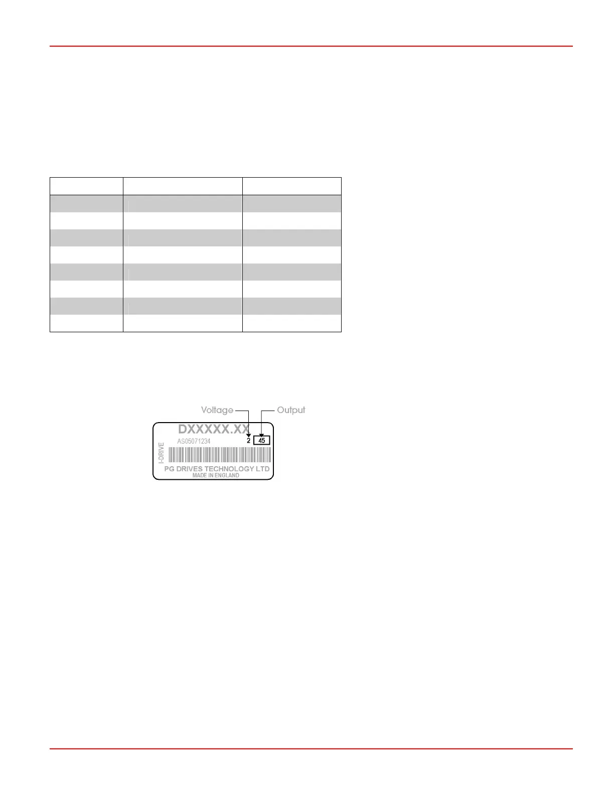
To identify which type of i-Drive you have, the voltage and output current rating is shown on the controller’s serial number label as
detailed below.
The number in the box indicates the output current; the single digit number to the left of the box indicates the operating voltage.
2 = 24V dc only.
3 = 24V dc or 36V dc.
1.2 i-Drive Operation
Study
Chapter 1: Operation. It is important that the information in Chapter 1 is supplied with the machine, either as part of the
machine user handbook or as a separate document.
This chapter sets out the installation conditions that must be complied with in order to meet the safety requirements of
EN60335/2/72.
SK76977-07 25
 Loading...
