PG LIFELINK Mark V Line Isolation Monitor Instruction Manual Rev. 2.0
© 2014 PG LifeLink, Inc. - All rights reserved
Page 15
personnel in accordance with all established safety procedures. Death or
personal injury, or equipment damage, can result from improper service
procedures. Turn off and lock-out all power to the isolated power panel including
the LIM before contacting any electrical connections.
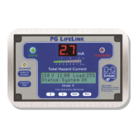
LIM displays “
CA” (Calibrate) during operation
This is a normal occurrence at intervals during operation, occurring in
accordance with the unit’s schedule settings. The unit should return to normal
within about 30 seconds. If unit does not return to normal mode, or
continuously cycles through “
CA” sequence, contact Technical Support.
LIM indicates very high hazard current at time of installation
The LIM is connected to a grounded (non-isolated) power source. Verify that
the power source is isolated.
There may be too much external equipment connected to the isolated power
system, or faulty wiring, or a fault in the connected equipment. (Note: only
perform this procedure once patient(s) and attending clinical personnel
have left the area) To locate the fault(s), turn off all the branch circuit
breakers in the isolated power panel, and verify that the LIM indication then
decreases to a safe level. Turn the breakers back on one at a time, allowing
the LIM indication to stabilize for each one. Any circuit which causes the LIM
indication to increase signicantly when turned on has a problem. Unplug all
connected equipment, if any, from that circuit . If the fault remains, inspect all
wiring and devices powered from that branch for chafed or pinched wires,
terminals touching exposed metal surfaces, foreign matter, or any other
unintentional conductive path from power to ground. When all permanent
equipment and wiring has been veried, reattach powered equipment one
device at a time to locate the fault(s).
Incorrect wire type or installation techniques may have been used for wiring.
Article 517-160 of the NEC states that wire with a dielectric constant less than
3.5 is preferred for use in isolated power systems, recommends that all
conduit runs be made as short (direct) as practical, and specically forbids the
use of pulling compounds that increase the dielectric constant. This is because
a signicant portion of the total system leakage current is produced by the
capacitance between energized components (including wires) and grounded
components such as conduit and ground wires, and exists regardless of the
condition of the insulation or how high its resistance may test at DC such as
with a “megger”. Leakage current increases directly in proportion to
capacitance. Dielectric constant is the measure of a material’s effect on this
capacitance, with higher numbers indicating a higher capacitance
multiplication effect if all else is equal. Wire type XHHW-2 is a commonly
available trade type meeting these requirements. The NEC also species the
colors of wire to be used in isolated power systems: orange for the wire
connected to devices as neutral, brown for the one connected as “hot”.
Certain kinds of equipment are known to exhibit high leakage current and
can cause issues when powered from isolated systems. These items are
typically commercial-grade (non-medical grade) and include some lighting
xtures especially those with ballasts, motorized equipment, and switching
power supplies such as are typically used in computers. Sometimes these
devices are permanently wired and cannot be unplugged to test, but must be
 Loading...