Page 16
© 2014 PG LifeLink, Inc. - All rights reserved
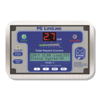
PG L
IFELINK Mark V Line Isolation Monitor Instruction Manual Rev. 2.0
disconnected at a junction box. Contact PG LifeLink technical support if you
suspect that a piece of equipment is contributing excessive leakage current on
the system.
If the LIM THC indication remains high with all breakers turned off, the
isolated power panel or the LIM itself may be malfunctioning or damaged. If
another known-good LIM of the same voltage rating is available, try
substituting it into the panel; or if a known-good panel of the same voltage
rating is available, try substituting the LIM into that panel. If the problem
moves with the LIM, suspect the LIM; if it stays with the panel, the LIM is not
the cause. Or, if a suitable insulation tester is available, the panel and wiring
can be directly tested for faults.
Poor-quality incoming power with excessive harmonics or transients can
cause both high actual THC and erroneous LIM readings. Equipment with
high-power rectiers or switching elements connected to the same source as
the isolated power panel, such as battery chargers and motor speed controls,
is a common cause of this kind of problem. Connect the isolated power
system to an alternate power source.
LIM indication always very low or near zero regardless of external conditions
This can happen as a result of faulty installation, if both ground wires are
disconnected from ground but are properly connected to each other. This
condition totally isolates the LIM from ground since these wires are its only
connection to earth ground. This prevents the LIM from “seeing” earth
ground, and it therefore cannot measure the impedance between the
isolated power circuit and ground. However, if the ground wires remain
connected to each other, it will also be prevented from identifying a “ground
loss” condition even if they are both disconnected from ground. It is not
possible for the LIM to identify this condition on its own. Trace all ground
wiring and verify proper connections. Verify ground system integrity by
measuring the resistance from pins 12 & 13 of the LIM connector to a known
good earth ground such as a water pipe, building steel, or electrical service
ground. This resistance should be very low, much less than 1 ohm.
Remote annunciator malfunction
Verify wiring between LIM and remotes. Look for things like disconnected or
shorted wires, +5 VDC and Gnd exchanged, or the 2 data wires swapped.
Check the voltage between the +5 VDC and Gnd terminals at the remote. It
should be at least 4.5VDC. If the supply voltage reaching the annunciator is
too low, the annunciator may become unreliable or even cease working
altogether. To remedy this excessive voltage drop, run larger wires for the +5
VDC and ground connections. Up to 12 gauge stranded wire may be used,
or larger wire can be used if pigtails of 18 to 12 gauge wire are used at the
remote. When increasing wire size, only the +5VDC and Ground wires (Red
and Black) are necessary to be made larger; the signal wires (blue, violet, and
grey) carry very little current and their size does not normally affect operation.
If the power supply voltage at the terminals is still below the acceptable limit
even with larger wire, an auxiliary power supply located at the remote can be
used. Contact PG LifeLink Technical Support or Sales for assistance.
Check the remote’s mounting in its box. Verify that no exposed electrical parts
of the remote, including the circuit board or the terminals, is touching the
 Loading...