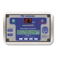
PG LIFELINK Mark V Line Isolation Monitor Instruction Manual Rev. 2.0
© 2014 PG LifeLink, Inc. - All rights reserved
Page 7
Caution: Caution:
Do not apply voltage greater than 150VAC to
device unless switch SW1 on the PS (lower) board is
placed in the 230V position! Application of voltage in
excess of device setting may severely damage this device
and/or endanger the user.
NOTE: Improper connection can damage the LIM and/or create danger for
the user. Always verify correct connections before applying power!
The PG LifeLink Mark V Line Isolation Monitor has two selectable voltage range
settings: 115V and 230V. Verify that the proper voltage range is selected BEFORE
connecting or applying power to device. Failure to select the proper voltage
range will severely damage the LIM , invalidate product warranties, and may
endanger the user.
Units supplied as part of an IPS panel are precongured according to the panel’s
output voltage. Do not move a LIM from one panel to another without verifying that
the nominal output voltages of the two panels are the same. LIM’s supplied
independently are congured according to customer’s requested voltage range. If
no voltage is specied, units are typically congured for 120VAC application.
Voltage range selection is accomplished via switch SW1, located on main supply
board PCB inside the unit.
To access Voltage Selection Switch SW1:
1. De-energize panel and completely disconnect wiring harness connector
J-2 from LIM.
2. Remove four (4ea.) black Phillips head screws securing front escutcheon
plate to LIM housing. Carefully remove escutcheon.
3. Remove eight (8ea.) Phillips head
screws securing upper and lower
PCB assemblies to LIM housing.
Carefully remove PCB assemblies.
4. Located Switch SW1 on bottom of
main supply board. Set switch
according to Table 1.
5. Carefully reinstall PCB assemblies
into LIM housing and secure with original hardware.
6. Reinstall front escutcheon plate.
7. Reconnect wiring harness connector J-2.
The Mark V LIM wiring harness is factory terminated in new IPS panels on a standard
11-pole control terminal block (TB-Remote) for eld connection of accessories,
including optional sensors, remote annunciators, or communication devices. Refer
to Figure 2 for proper connection. Dashed lines indicate control wiring supplied by
installer.
Certain units, including those supplied as part of a replacement or upgrade kit, may
include a factory modied wiring harness, which is designed for the specic
application. However, the power and ground connections are consistent for all
Nominal Line
Voltage (IPS)
Switch SW1
Setting
110-120 VAC 115V
208-240 VAC 230V
Table 1 - Voltage Selection Settings
 Loading...