EasyManua.ls Logo

PGO Tigra AF-125BAE - User Manual

PGO Tigra AF-125BAE
95 pages
Print Icon
To Next Page IconTo Next Page
Loading...
1
PREFACE
This service manual contains chief instructions in connection with service and
maintenance of PGO TIGRA motorcycle and is also one technical manual and one
best guideline illustrating details for service workers who are engaged in maintenance,
reparation, replacement of parts, troubleshooting, and reassembly. The service manual
prepared from simple takedown to detailed disassembly and from performance
introduction to service preparation provides complete instructions for general
lubrication and routine check or adjustment. Explained with general views, exploded
views, or photos, all necessary items repeatedly cited should be referred to the
previous drawings and not further described in detail herein.
As a result of this service manual composed of directions for the following model,
please check the model of your motorcycle among different ones in the manual for
any contents available.
AF-125BAE: Four-Stroke Cycle, 125CC Level, 4-valve, water cooling,
electronic injection engine
The high-performance electronic fuel-injected water-cooling engine provided in
this motorcycle is the up-to-date 125CC engine developed by Motive Power and being
excellent in the engine kept within the optimal operating temperatures for high
precision and the power output superior to that of a general air-cooling engine.
For any inadvertent mistakes attributed to preparation in a hurry, Motive Power
Industry sincerely wish any person skilled in the art offer any comments.
MOTIVE POWER INDUSTRY CO., LTD.

Table of Contents

Question and Answer IconNeed help?

Do you have a question about the PGO Tigra AF-125BAE and is the answer not in the manual?

Summary

Information Summary and Preparation

1-3 Specifications

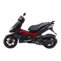
Lists the detailed technical specifications of the motorcycle model.

1-4 Code of practice

Outlines essential rules and guidelines for performing maintenance and repairs.

1-5 Torque

Provides a table of recommended torque values for various bolts and nuts.

1-6 Service tools

Lists and describes specialized tools required for maintenance and repair tasks.

1-7 Procedure to maintain the Electronic Management System (EMS)

Details the systematic procedure for diagnosing and maintaining the EMS.

Check & Adjustment

Brake system

Checks for brake lever back-play, brake disk, and brake oil level.

Check; adjust timing

Procedures for checking and adjusting engine timing using timing marks.

Items and cycle for periodical maintenance

A table detailing periodic maintenance checks and replacement cycles.

Lubrication System

Disassembly of the Engine Assembly

Separate the engine from the vehicle body

Step-by-step procedure to detach the engine from the motorcycle chassis.

Cylinder Head

Cylinder Assembly

Install the cylinder and the piston

Steps for installing piston rings, piston pin, and piston into the cylinder.

Installation of the cylinder

Procedures for installing the cylinder onto the crankcase.

Installation of the cylinder head

Steps for installing the cylinder head, gasket, and timing sprocket.

Crankcase & Crankshaft

Installation of the crankcase

Detailed methods for installing the crankcase, bearings, and sprockets.

Method (2) Separate the bearing and the engine oil sprocket

Alternative method for separating bearing and engine oil sprocket installation.

Fuel Injection System

ECU

Explanation of the Electronic Control Unit's principle, functions, and specifications.

ECU Pin Configuration

Detailed list of ECU pins and their corresponding functions.

Intake manifold pressure sensor

Function, principle, and characteristic data of the intake manifold pressure sensor.

Temperature sensor

Function, principle, and fault diagnosis for the engine temperature sensor.

LSF Lambda sensor

Function, principle, and characteristic curve of the Lambda sensor.

Electromagnetic fuel nozzle

Function, principle, fault diagnosis, and installation requirements for the fuel nozzle.

DKG (Throttle sensor)

Function, principle, fault diagnosis, and measurement of the throttle sensor.

Idle speed actuator

Function of the idle speed actuator in controlling bypass airflow.

IMSE

Introduction to the IMSE system, its components, function, and principle.

Cooling System

Change coolant

Simplified steps for changing coolant, including volume and concentration.

Steps to change water coolant (cold cycle cleaning)

Procedures for performing a cold cycle cleaning of the cooling system.

Water pump

Steps for disassembling and installing the water pump, seals, and impeller.

Charge, Ignition, and Start-up

Fault diagnosis

Comprehensive list of potential faults related to power, voltage, starter, and engine running.

Battery

Procedures for checking battery voltage and charging current.

Charging system

Overview of system circuits and checks for charging components.

Starter system

Diagrams and checks for the starter system components and operation.

Check circuits of the starter system

Procedures for checking starter relay, switch, and motor circuits.

Ignition system

Diagram and checks for the ignition system components.

Check the ignition system

Procedures for measuring resistance of ignition circuits and components.

Exhaust Emission Control System

PGO Tigra AF-125BAE Specifications

General IconGeneral
Displacement124.6 cc
Front SuspensionTelescopic fork
Engine Type4-stroke, air-cooled
Bore x Stroke52.4 mm x 57.8 mm
Starting SystemElectric starter
TransmissionCVT
Front BrakeDisc
Rear BrakeDrum
Fuel Capacity5.5 L

Related product manuals