Chapter 7: Programmable I/O Signal Architecture | 47
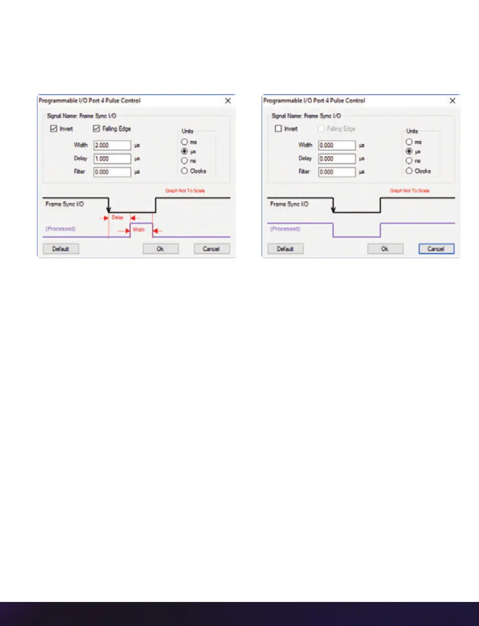
A graphic representation of the signal behavior is also displayed. However, this is not to
scale and should be used as reference only. Use of this feature requires an oscilloscope to
truly visualize the signals and the subsequent changes with each adjustment.
SUMMARY OF PULSE PROCESSOR SETTINGS
Invert: Inverts the signal at the output of the pulse processor.
Falling: Selects ‘Falling Edge’ mode for the pulse processor. This mode is only relevant
if the ‘Width’ is also specified. When the ‘Falling’ token is present together with ‘Width,’
the pulse processor will generate a negative pulse, triggered from the negative edge of
the input signal.
Width (Pulse Width): When a ‘Width’ token is present, a defined-length pulse is generated,
which starts after the specified ‘Delay’ and after the active edge of the ‘input’ signal. The
length of the pulse is specified in microseconds (as a floating point number) and internally
converted to pixel clock units. The maximum pulse width is at least 10 seconds. However,
if the period of the ‘input’ signal is lower than the selected width, the latter is dynamically
clamped to the signal period. The minimum pulse width is one pixel clock.
Delay: Delays the output pulse by the specified time in ms, µs or camera clock multiples.
If the ‘Width’ token is not present, both edges of the signal are delayed by the same
amount. If present, the delay is measured from the rising edge of the input
*
signal unless
the ‘Falling’ token is present, in which case the delay is measured from the falling edge
of the input. The delay time is specified in microseconds (as a floating point number) and
is internally converted and routed to pixel clock units.
*
Input: When a signal is generated by the camera, it serves as an input to the ‘pulse processor.’
In this context, the term ‘input’ does not represent an externally generated signal.
 Loading...