Vision Research, Inc. | Phantom Ultrahigh-Speed Camera Manual
PHANTOM UHS-12 & UHS-4O SERIES BNC CONNECTORS
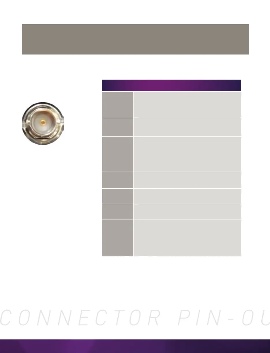
I/O Signal ports
BNC
Use these schematics to build custom cables at your own risk. Miswired cables
can cause serious damage to the camera, which is not covered under warranty.
Vision Research recommends only using cables supplied by Vision Research.
NOMENCLATURE/FUNCTION
1 Trigger
Dedicated I/O - Trigger-In / active-low isolated
input. Can be activated by a switch to ground.
The trigger pulse needs to be at least
three microseconds long.
2 TC In
Dedicated I/O - Timecode In / can accept IRIG-B
and SMPTE standards.
3 F-sync/P
ETHTXP / 10/100/1000BA Programmable I/O -
Default F-Sync / +5V maximum threshold, input
is also compatible with TTL levels and must be
a properly terminated (50-ohms). SE-T Ethernet
Transmit (positive).
4 Strobe /P
Programmable I/O - Default I/O Strobe / Isolated
collector output with 1k pull-up.
5 Ready /P
Programmable I/O - Default Ready / Isolated
collector output with 1k pull-up.
6 TC Out /P
Programmable I/O - Default Timecode Out / for
IRIG-B or SMPTE timecode.
HD-SDI
1&2
Two HD-SDI ports can act as identical 4:2:2
HD-SDI ports with one set up to provide
an optional on-screen display to monitor the
on-camera controls and camera operation.
Or they can be configured as a single 4:4:4
Dual-Link HD-SDI port.
 Loading...