Mounting and installation instruction
30.06.16 - 10 - 91130.docx
Rev.:1.40
Mounting process
Mounting preparations:
Seperate the mounting plate from the reader and disconnect the cable.
Install the connection cable at the mounting place of the reader.
Recommendation: Connect the reader with only one shielded cable.
Dependending on the construction stage and the system requirements if
necessary a removed terminal board required
Attention ! The wiring of the rear module must be done under no-voltage conditions.
The operating voltage may only be turned on after the reader has been
completely installed
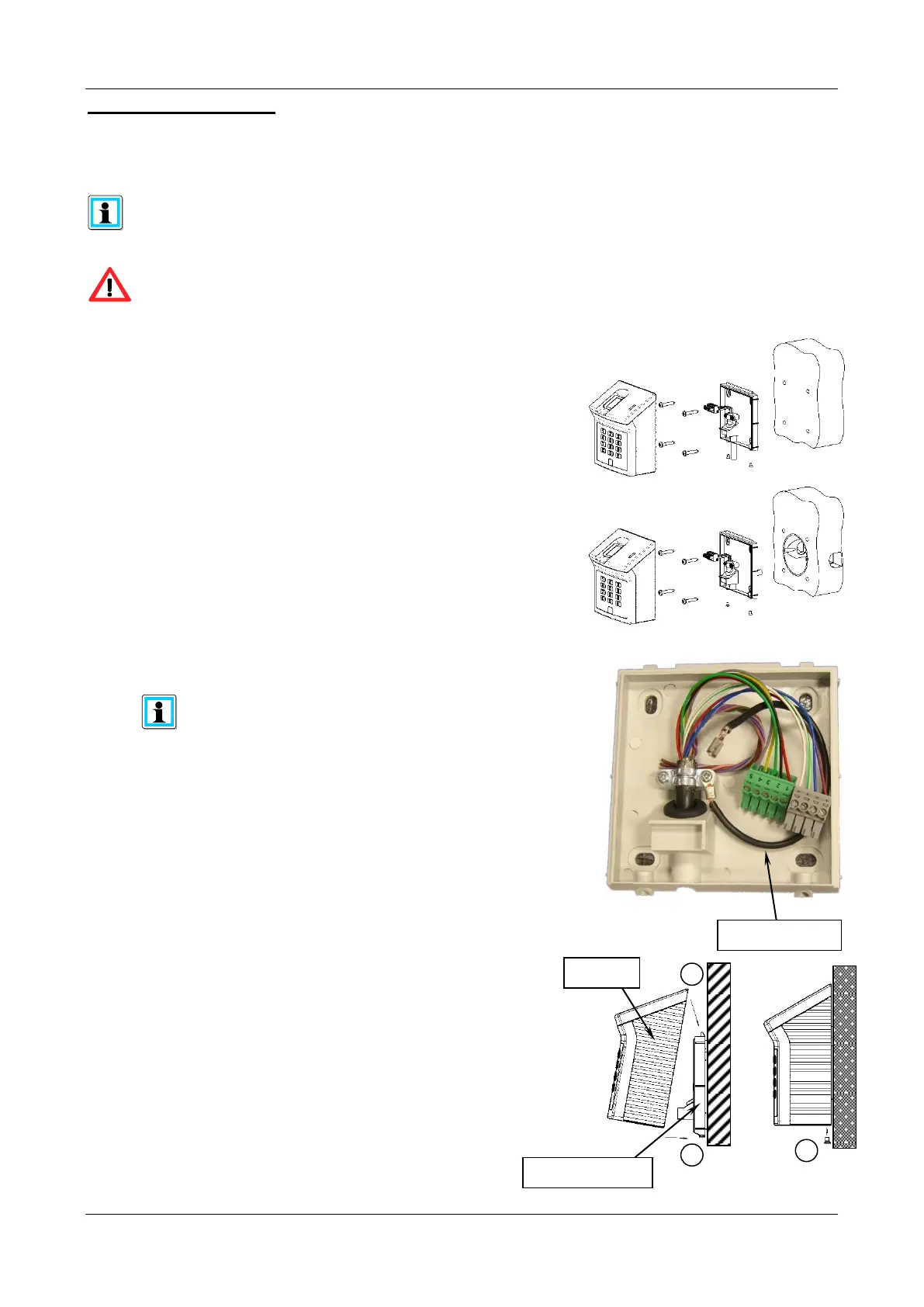
1. Select cable entry
- Cable entry from below (wall mounted)
- Cable entry through the mounting plate(flush-mounted).
2. Select mounting position and drill the holes in the wall
(refer to “Dimensions“, page 8).
3. Cables put through the rubber grommet of the mounting
plate. Drill the mounting plate with suitable screws on the wall.
4. Cut the shielded cable to the appropriate length.
Remove the cable sheath and prepare the cable shielding.
Clamp the cable under the cable clip so that a strain relief and
a contacting of the shield are guaranteed.
Wire the connection terminals according to the respective
terminal assignmnt. DIP switch settings.
The suitable connecting plan is enclosed to the reader
5. Plug the connection terminals on the fingerprint reader.
The pluggable connection terminals ST1, ST2, ST13
and ST17 are executed in four different colours.
The connection terminals must be put on the pin contact strip
with the same colour. Connect the shielding wire to the contact
of the reader (refer to page 4).
6. Hang the reader at the top in the two securing brackets.
7. Press the reader towards the mounting plate until the mounting plate
completely dips into the reader.
8. Screw in the security screw from below.
9. Connect the reader on the host side, switch the power
supply on and start the system / application.


 To Next Page