Mounting and installation instruction
30.06.16 - 9 - 91130.docx
Rev.:1.40
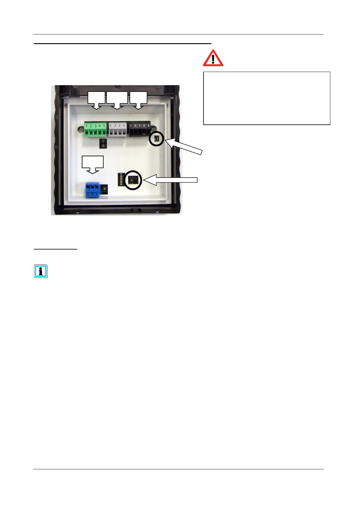
The plug in connection terminals
ST1, ST2, ST13 and ST17 are executed in
four differnt colours.
The connection terminals must be put on
the pin contact strip with the same colour.
Optical IR reflection light barrier.
Sabotage is detected when the reader is
removed from the rear wall mounting plate.
Contact for shielding wire (plug in)
Terminal assignment / terminal specification
Rear view
DIP Switch
The suitable connection plan with the description of the DIP switch functions is
separatly enclosed to each reader