19
1063_0_Product_Manual - October 27, 2010 2:54 PM
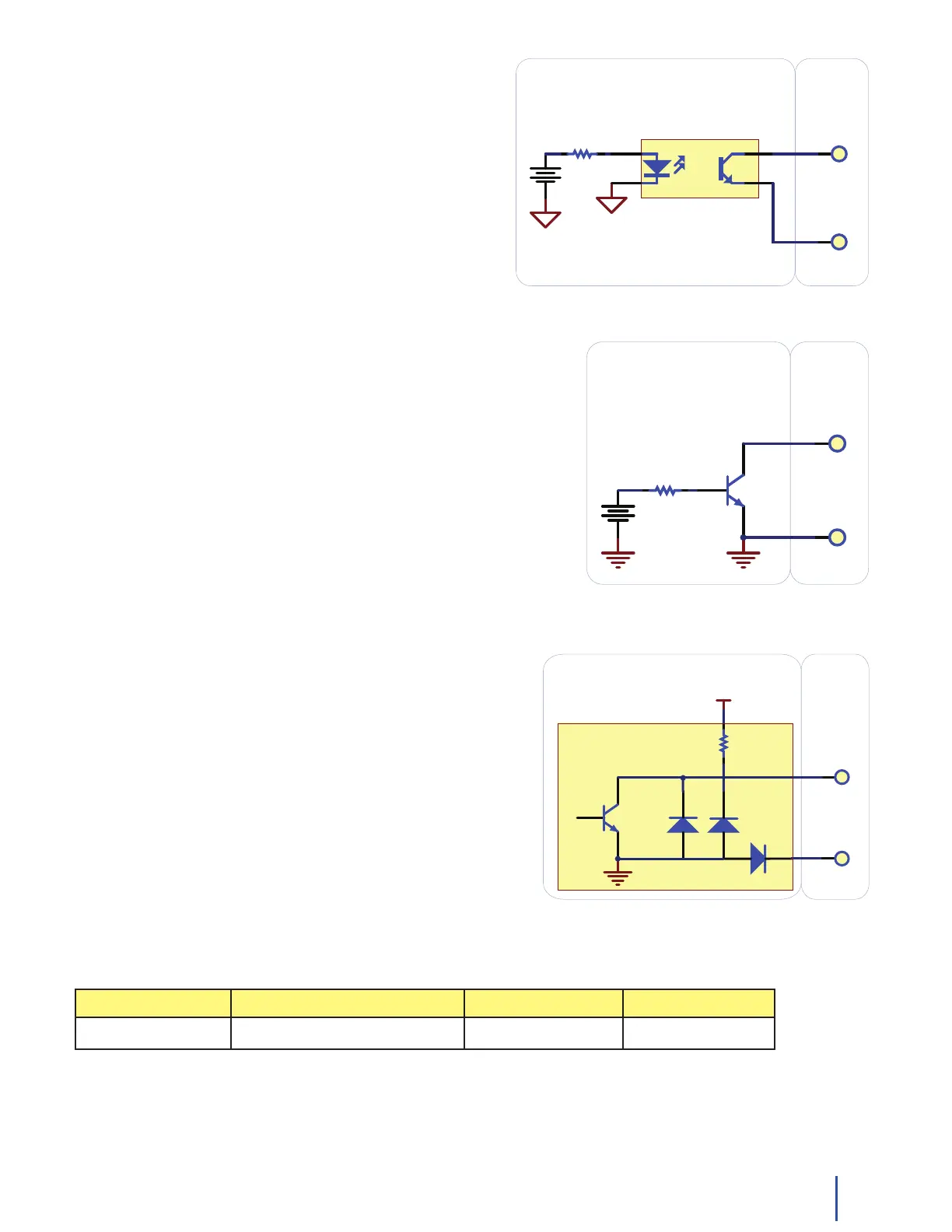
Isolating a Digital Input with an Optocoupler
When driving current through the LED, the Digital Input will
report TRUE. The amount of current required will depend
on the optocoupler used. Design to sink at least 280µA to
cause the digital input to report TRUE, and less than 190µA
to report FALSE.
Detecting an external Voltage with an NPN Transistor
This circuit can be used to measure if a battery is connected, or if 12V
(for example) is on a wire.
By designing to have Collector-Emitter current > 280µA, the digital
input will report TRUE.
Using a Capacitive or Inductive Proximity Switch
Capacitive proximity switches can detect the presence of nearby
non-metallic objects, whereas inductive proximity switches
can detect only the presence of metallic objects. To properly
interface one of these proximity switches to the digital inputs, a
3-wire proximity switch is required, as well as an external power
supply.
We have checked the following switch from Automation Direct
to verify that it works with the Digital Inputs. Similar capacitive
or inductive proximity switches from other manufacturers should
work just as well.
Manufacturer Web Page Capacitive Part No Inductive Part No
Automation Direct www.automationdirect.com CT1 Series AM1 Series
100nF
15K
15K
+5V +5V
INPUT
GROUND
INPUT
GROUND
USER
SW IT CH
W iring a switch to a Digital Input
APPLICATION
Monitoring the position of a Relay
K 1
FSR
Isolating a Digital Input with an Optocoupler
Closing sw itch causes digital input to report TRUE Detail of Digital Input
USER
APPLICATION
Relay contact causes Digital Input to report TRUE
Current through LED causes Digital Input to report TRUE
USER
Using an FSR as a switch
APPLICATION
FSR Resistance f alling below 3.75k Ohms causes Digital Input to go TRUE
FSR Resistance rising above 75k Ohms causes Digital Input to go FALSE
This design can be used with any variable resistance sensor - CDS Photocells.
Q1
Detecting an external Voltage with an NPN Transistor
Collector-Emitter Current > 270uA causes Digital Input to report TRUE
Collector-Emitter Current < 67uA guarantees Digital Input to report FALSE
Detecting an external Voltage with an N-Channel MOSFET
1K
R1
Drain-Source Current > 270uA causes Digital Input to report TRUE
Drain-Source Current < 67uA guarantees Digital Input to report TRUE
The resistor on the Gate is not required for it to function, but is a good idea.
Be sure not to exceed VGS of the mosfet.
Drain-Source Current > 270uA causes Digital Input to report TRUE
Drain-Source Current < 67uA guarantees Digital Input to report TRUE
Actual Voltage Required to switch is dependent on VGS required to turn on MOSFET
USER
APPLICATION
USER
APPLICATION
USER
APPLICATION
VS1
10K
R1
VS1
1K
R1
VS1
U1
OptoCoupler
Q1
INPUT
GROUND
100nF
15K
15K
+5V +5V
INPUT
GROUND
INPUT
GROUND
USER
SW I T C H
W iring a switch to a Digital Input
APPLICATION
Monitoring the position of a Relay
K 1
FSR
Isolating a Digital Input with an Optocoupler
Closing switch causes digital input to report TRUE Detail of Digital Input
USER
APPLICATION
Relay contact causes Digital Input to report TRUE
Current through LED causes Digital Input to report TRUE
USER
Using an FSR as a switch
APPLICATION
FSR Resistance f alling below 3.75k Ohms causes Digital Input to go TRUE
FSR Resistance rising above 75k Ohms causes Digital Input to go FALSE
This design can be used with any variable resistance sensor - CDS Photocells.
Q1
Detecting an external Voltage with an NPN Transistor
Collector-Emitter Current > 270uA causes Digital Input to report TRUE
Collector-Emitter Current < 67uA guarantees Digital Input to report FALSE
Detecting an external Voltage with an N-Channel MOSFET
1K
R1
Drain-Source Current > 270uA causes Digital Input to report TRUE
Drain-Source Current < 67uA guarantees Digital Input to report TRUE
The resistor on the Gate is not required for it to function, but is a good idea.
Be sure not to exceed VGS of the mosfet.
Drain-Source Current > 270uA causes Digital Input to report TRUE
Drain-Source Current < 67uA guarantees Digital Input to report TRUE
Actual Voltage Required to switch is dependent on VGS required to turn on MOSFET
USER
APPLICATION
USER
APPLICATION
USER
APPLICATION
VS1
10K
R1
VS1
1K
R1
VS1
U1
OptoCoupler
Q1
INPUT
GROUND
100nF
15K
15K
+5V +5V
INPUT
GROUND
INPUT
GROUND
USER
SW IT CH
W iring a switch to a Digital Input
Phidget
Digital
Input x1
APPLICATION
Monitoring the position of a Relay
K 1
FSR
Isolating a Digital Input with an Optocoupler
Phidget
Digital
Input
Closing switch causes digital input to report TRUE Detail of Digital Input
USER
APPLICATION
Relay contact causes Digital Input to report TRUE
Current through LED causes Digital Input to report TRUE
USER
Using an FSR as a switch
APPLICATION
FSR Resistance f alling below 3.75k Ohms causes Digital Input to go TRUE
FSR Resistance rising above 75k Ohms causes Digital Input to go FALSE
This design can be used with any variable resistance sensor - CDS Photocells.
Q1
Detecting an external Voltage with an NPN Transistor
Collector-Emitter Current > 270uA causes Digital Input to report TRUE
Collector-Emitter Current < 67uA guarantees Digital Input to report FALSE
Detecting an external Voltage with an N-Channel MOSFET
1K
R1
Drain-Source Current > 270uA causes Digital Input to report TRUE
Drain-Source Current < 67uA guarantees Digital Input to report TRUE
The resistor on the Gate is not required for it to function, but is a good idea.
Be sure not to exceed VGS of the mosfet.
Drain-Source Current > 270uA causes Digital Input to report TRUE
Drain-Source Current < 67uA guarantees Digital Input to report TRUE
Actual Voltage Required to switch is dependent on VGS required to turn on MOSFET
USER
APPLICATION
USER
APPLICATION
USER
APPLICATION
VS1
10K
R1
VS1
1K
R1
VS1
U1
OptoCoupler
Q1
INPUT
GROUND
Phidget
Digital
Input
INPUT
GROUND
Phidget
Digital
Input
INPUT
GROUND
Phidget
Digital
Input
INPUT
GROUND
Phidget
Digital
Input
INPUT
GROUND
Phidget
Digital
Input
USER
APPLICATION
INPUT
GROUND
Q1
+10-30V
Connecting a 3-wire Capacitive or Inductive Proximity Switch
Proximity Switch