Circuit Description
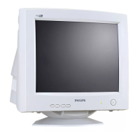
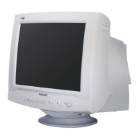
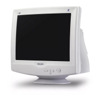
PHILIPS Confidential – Do Not Copy 105S5
1. POWER SUPPLY
1.1 Power supply.
A. Primary Side.
The raw DC voltage is built on C101 from AC line voltage through EMI filter and bridge rectifier CR 101
then composes with main transformer (T101) switching MOSFET (Q101) and PWM IC (IC101) to form a DC-DC
voltage converter by flyback switching topology, which means that the power energy is pumped up at primary
winding of transformer during duty “ON” cycle, then transfer the stored energy to primary side, and voltage
regulated by PWM IC (3842) using way of pulse width modulation.
The IC101 starts up through some components composed of R103,R104,R105,Q102,ZD102 to build up VCC
voltage at pin 7 and supplied by transformer once secondary voltage is established. IC101 have to work
synchronously with horizontal sync by feeding flyback pulse through C110,R120, C108 and D113 composed a
soft-start circuit to prevent over-stress occurred during power start.
The TP201, 75V voltage can be adjusted through VR101.
The IC101 pin 3 is current sense input of comparator PWM latch, if the volts reach 1.0V, The pin 6 pulse
output will be terminate
B. Secondary
Each raw of DC voltage output from T101.
a. TP201 voltage output from T101 pin12 and is rectified by D202, C201.
b. TP202 voltage output from T101 pin11 and is rectified by D203, C202.
c. TP203 voltage output from T101 pin17 and is received by D205, C205.
d. TP204 voltage output from T101 pin18 and is rectified by D206, C206.
e. TP205 voltage output by Q206, ZD201 and D208 is 12V
f. TP206 voltage output by Q208, Q209, R213, R228 is 6.3V
f. TP207 voltage output by R217,C211, ZD305, C305 is 5V
1.2 Power saving.
The EPA power management state as follows.
State PD Power consumption LED
Normal H < 75W Green
Active Off L ≤ 8W Yellow
PD = IC301 (MCU) pin 17 output.
There is no output from Q203, Q206 and Q208 while is in active off mode and PD (IC301 Pin 17) are at low
Level voltage. That is, there is no output for 12V and 6.3V
2. H and V processor
2.1 Auto SYNC Deflection control and B+ control circuit Horizontal and vertical sync through IC401 STV6888
Transmit.
Deflection controller IC401.
a. The control input (V-position, H-position, V-size, H-size, Pincushion, Pin-Balance, Trapezoid,
Parallelogram, moire) are use I
2
C control.
b. SYNC input.
H-sync (pin1) From IC301 pin33.
http://jdwxzlw.com/?fromuser=华盛维修